Masks
by Alejandro Tombolini
Introduction
This article will attempt to provide a guide to begin building masks with PixInsight. There is a huge universe of possible masks that will depend on the image you are processing and your specific needs. Here we will show some of them from the simplest and quickest to make to some a little more complex. The purpose of this guide is to show easily the most important ways to build and use a mask with the available processing tools.
Masks function as selective protection for certain areas of an image. PixInsight is extremely flexible regarding masks and any image can be used as mask, but typically a mask is a gray scale image, where a pixel value of 1 (white) represents a point where a process will be applied completely, and a pixel value of 0 (black) represents a point where the process will not be applied. In the intermediate pixel values between 1 and 0 the applied processes will have intermediate results. Examples of using masks are the protection of stars while applying a process that affects a nebula or galaxy, or protection of an object while performing noise reduction on the background.
sually you will build a mask using different tools and techniques as will be described in this article, then apply it to the image and finally perform some processes on the image. But PixInsight also has tools with built in masks that allow you to build the mask directly from the tool that is being used, such as ACDNR, MultiscaleLinearTransform, and MultiscaleMedianTransform.
There are also other tools that allow you to use a Lightness mask but without the ability of modify it, such as HDRMultiscaleTransform and ExponentialTransformation.
Note: Lightness masks incorporated in the tools are compatible with masks that are derived from the image.
There are also tools that allow you to generate the masks that are used internally during a process. This functionality can be very useful in some cases as the generated mask can be utilized in further processing. Examples include GradientHDRComposition, GradientMergeMosaic and HDRComposition tools.
Coverage
This article covers the construction and use of different kind of masks using the specifically designed and available tools like StarMask and RangeSelection or combinations of other tools.
Note: The images of this article are random and do not represent a specific workflow or processing example and they belong to various authors. Thanks to Ezequiel Bellocchio, Andrés Vattuone, Vik Kohli and Tim (Chusellon).
Building masks
- Lightness Mask
- StarMask
- HaloMask
- TerrestrialMask
- CircularMask
Searching masks
Using masks
Lightness Mask (Lmask)
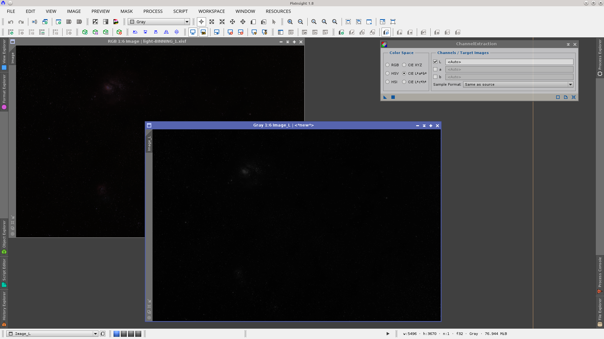
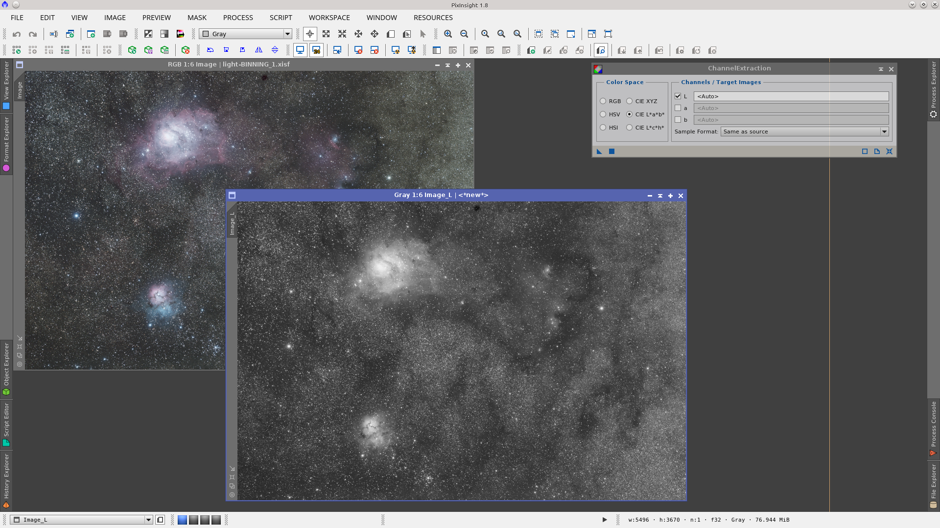
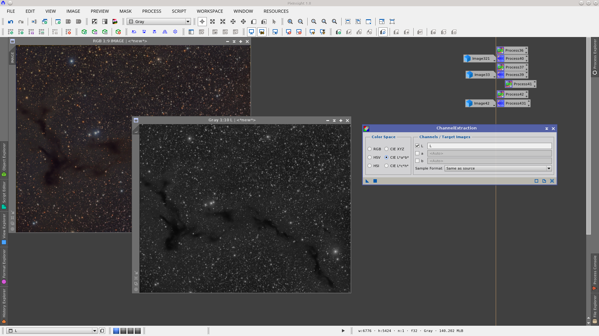
You can generate a Lightness Mask by extracting the CIE L* component of an image using the button Extract CIE L* Component ![]() from the Image tool bar or using the ChannelExtraction tool checking CIE L*a*b* Color Space and L Channel.
from the Image tool bar or using the ChannelExtraction tool checking CIE L*a*b* Color Space and L Channel.

Working with linear astro images, the generated mask (an image in gray scale) will look dark, and in most cases this image will need some processing in order to adjust it to the needs of the image to be protected (for instance by using the HistogramTransformation tool). The name of the new image (the mask) will have the _L suffix added by default to the original name of the image, (i.e. Image_L) and you can rename it as you wish, or you can enter the desired name in the ChannelExtraction tool and the image will be directly generated with the name you have chosen.
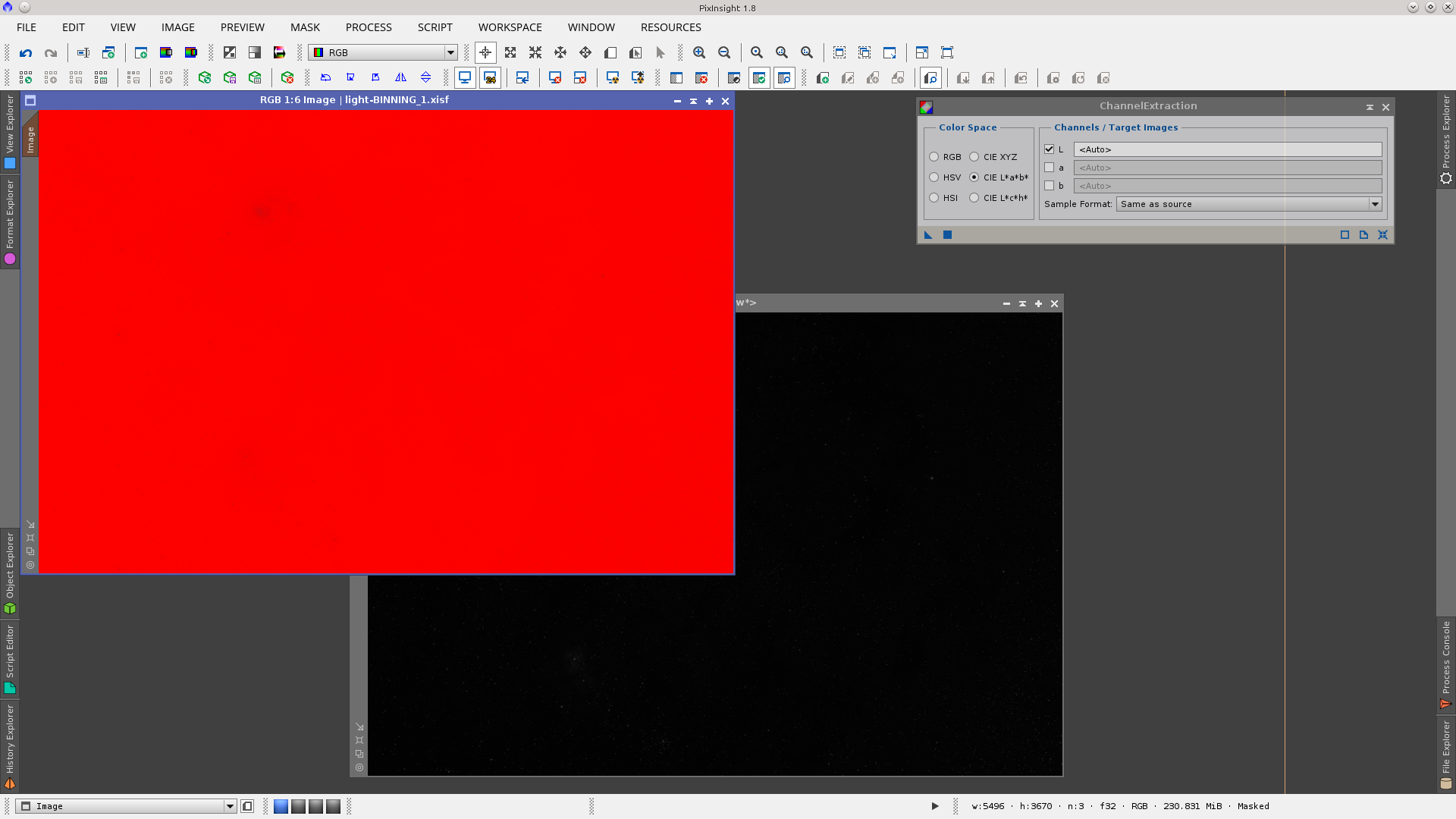
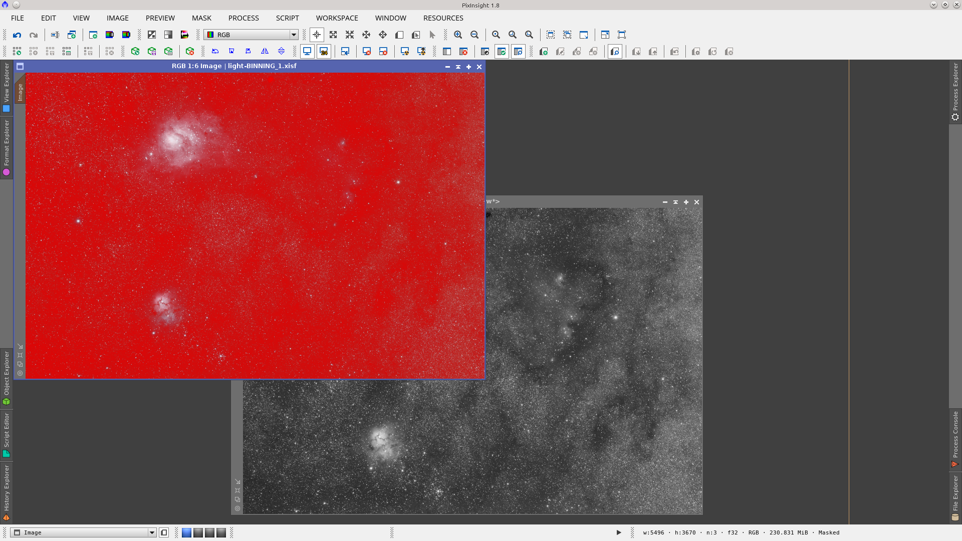
When applied to an image, a linear Lmask will usually look almost completely red since most of the pixels in astronomical linear images have values next to 0 (black). Red mask values represent points where the process will not be applied.
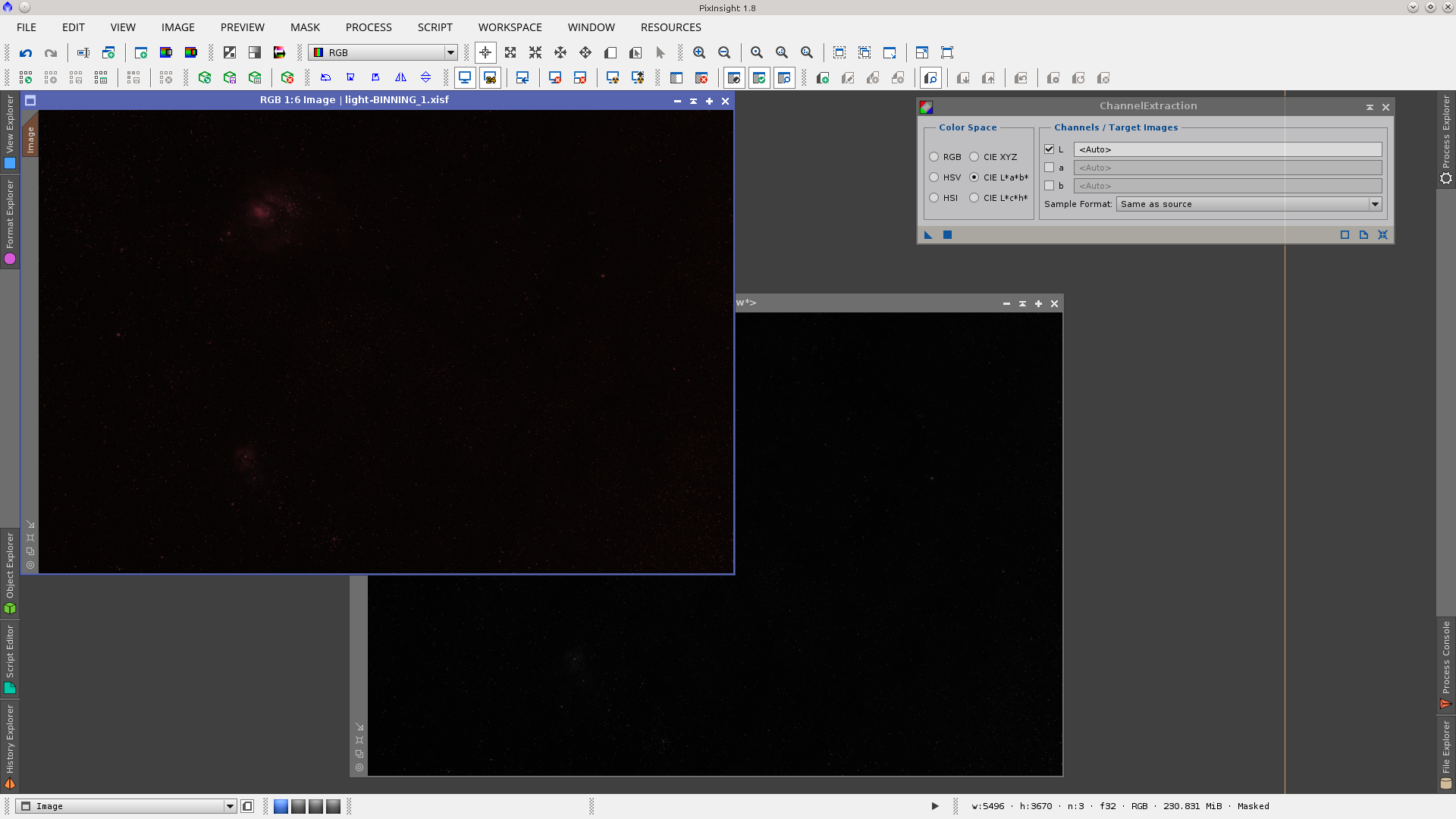
An inverted Lmask, by contrast, will look mostly transparent (most of the values near 1) and it will show a red tone over only the brightest parts of the image.
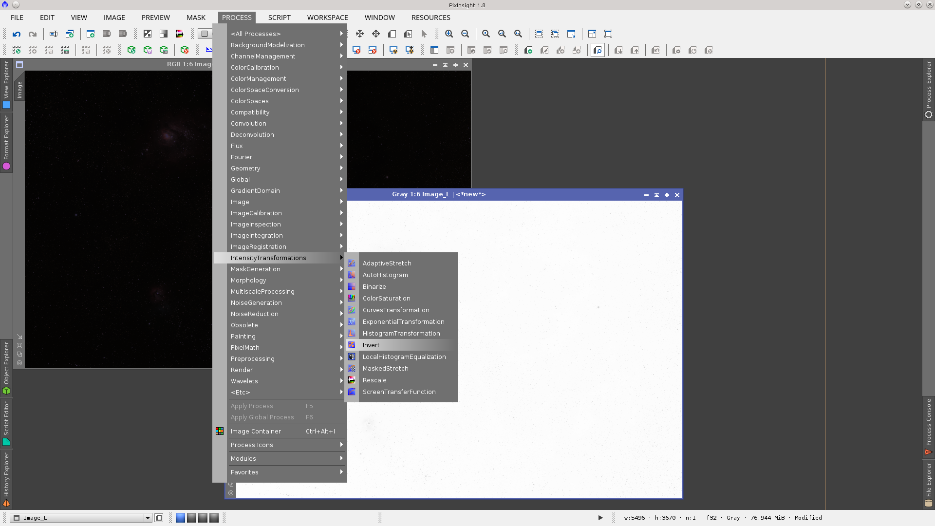
The Invert Image button ![]() is located in the Intensity Transformation Tool Bar, which allows you to invert an image. It may be useful to invert the Lmask to provide masking for different operations.
is located in the Intensity Transformation Tool Bar, which allows you to invert an image. It may be useful to invert the Lmask to provide masking for different operations.
Inverting an image can be also performed from Menu Process › IntensityTransformation › Invert , with the target image active or by using the CTRL + I hotkey.
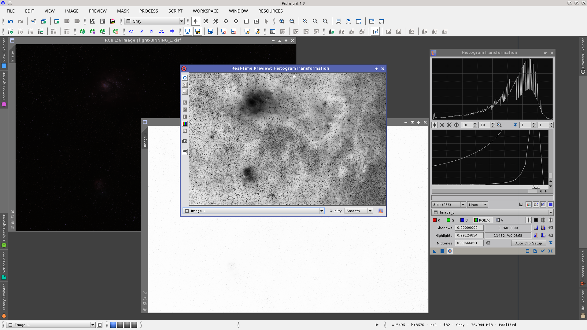
Once extracted the linear Lmask may need to be stretched and modified, for example when you need to mask the brightest areas of an image to do denoising over the background.
On the inverted Lmask you can obtain a first attempt at the desired mask by moving the midtones balance slider of the Midtones Transfer Function (MTF) in the HistogramTransformation tool to the right, and also the highlight clipping slider a little to the left, to reach the histogram peak as shown in the next screenshot.
By moving the midtones to the right you will vary the values of the MTF from 0.5 to 1 and will notice if using Real Time Preview (RTP) that the mask gets dark (pixels have values nearer to 0 (black) which represents points where the process will not be applied). Moving the highlight slider to the left you will vary the values from 1 to 0 and will notice in the RTP that the mask becomes white in the background as the pixel values of the mask approach 1 (which represents points where the process will be fully applied).
This way, if your Lmask is intended to protect the object during a denoising action, you will Apply it directly to the image and the process will have full effect in the background and middle and no effect where the image has more signal (the object).
So, if you Apply this inverted Lmask directly onto the image, it will protect mainly the nebula and stars and will give less protection to the background. If you need the opposite, Apply Inverted Mask or invert it from the Invert Mask button in the Tool Bar.
Lets see what happens if the image is already stretched.
Working with non linear astroimages, the generated mask (an image in gray scale) will show the object clearly and generally this mask can be used as is, but it can also be processed (for instance using the HistogramTransformation tool) to fit the needs of the image to be protected.
An image with a non linear Lmask will look partially red since most of the pixels of the mask have low values. Those values represent points where the process will be partially applied or not applied at all. Only the mask over the objects and stars will be partially transparent, representing points where the process will be applied.
An inverted Lmask, by contrast, will look red over the objects and stars, protecting those pixels from any processing, and will be totally or partially transparent over the background to allow processing there.

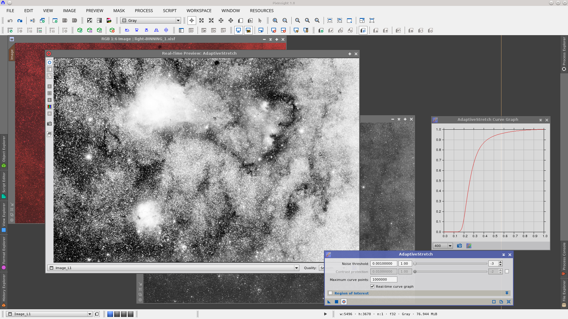
The non linear Lmask may need to be stretched and modified. For example, you may need to mask the brightest areas of an image to do background denoising while protecting the fine details of a nebula. The stretch of the mask can be done with PixInsight’s many intensity transformation tools. In this example I choose AdaptiveStretch.
AdaptiveStretch does a very good job with its default values for most non linear Lmasks, but always modify it as required to adapt the result to the needs of the image.
Let’s process this mask a little more. Suppose that we need to do noise reduction in the image. For denoising purposes the mask may need to be smoothed to achieve a better result and to make sure that a noisy mask doesn’t also protect some image noise. One usual way to do this is with the MultiscaleLinearTransform tool where you can set noise reduction values per layer or even delete layers. With a small preview that covers both bright and dark areas you can check in the Real-Time Preview window of the MultiscaleLinearTransform tool how the mask is modified while adjusting per-layer noise reduction values as shown in the next screenshot.
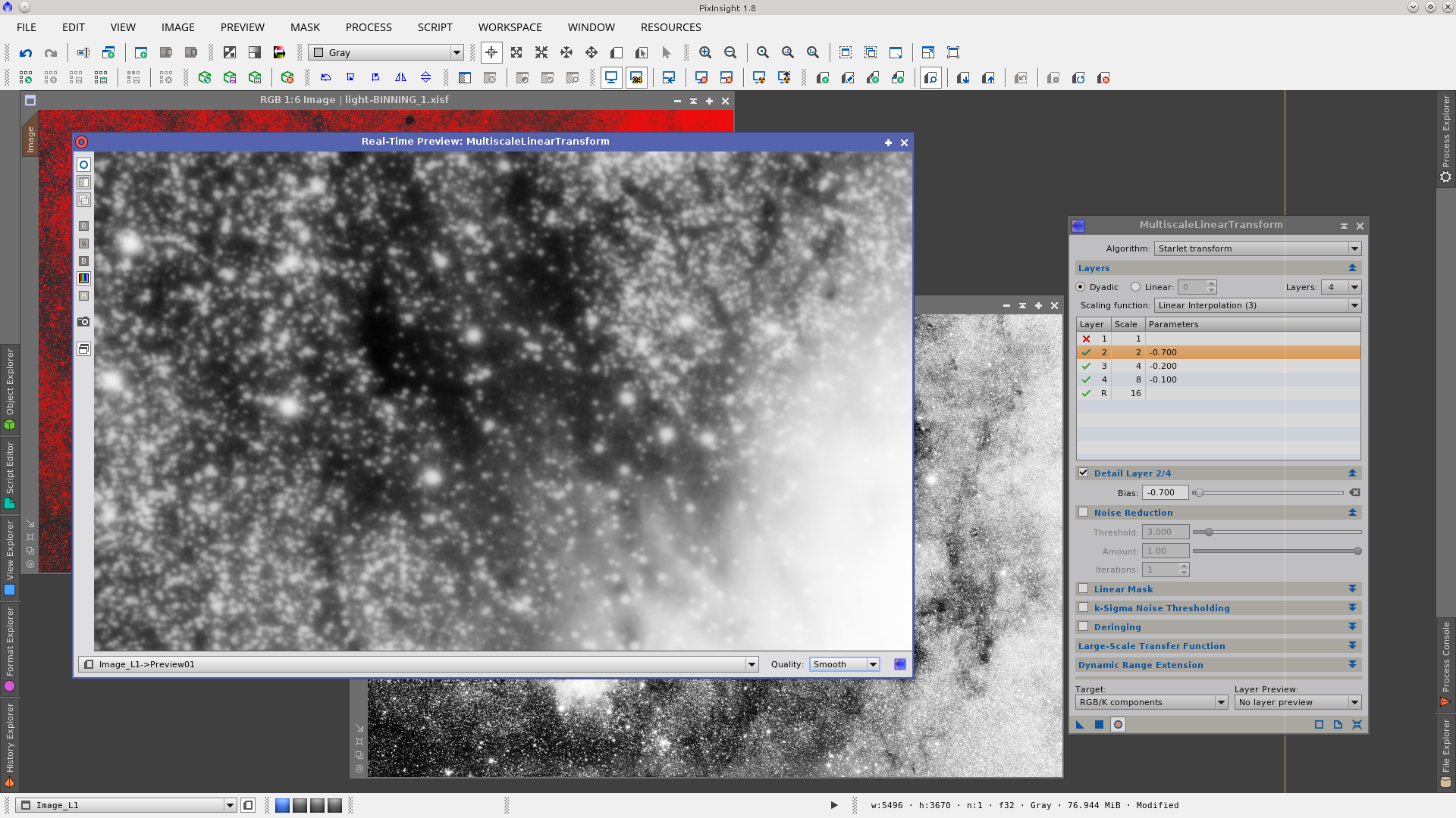
The modified Lmask may now be applied to the image to protect the object while performing noise reduction with any of the available noise reduction tools.
Lightness Mask (Lmask) to increase contrast
You can generate a Lightness Mask by extracting the CIE L* component of an image using the button Extract CIE L* Component ![]() from the Image tool bar or using the ChannelExtraction tool checking CIE L*a*b* Color Space and L Channel.
from the Image tool bar or using the ChannelExtraction tool checking CIE L*a*b* Color Space and L Channel.
In this example we are working with a non linear astroimage, already stretched, and the generated mask (an image in gray scale) will not look dark as it would when working with linear image. It is an image that can be visualized without any further processing or the need to use the ScreenTransferFunction (STF) tool. The name of the new image (the mask) will have the _L suffix added by default to the original image name (i.e. Image_L). You can rename it if you wish, or you can specify the new name (L in this example) in the ChannelExtraction tool.
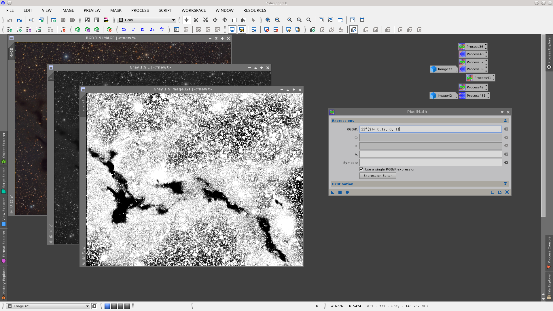
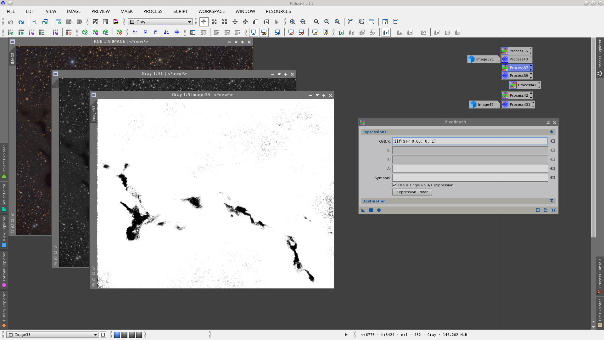
Once the Lightness of the image is extracted, you can binarize it by using the PixelMath tool. In the binarization process the pixel values will be converted to 0 or 1 depending on whether they are greater or less than a threshold. Using the expresion iff ($T<0.12, 0, 1) we define that all the values of the pixels in the image ($T) will be converted to 0 (black) if they are lower than 0.12 and will be converted to 1 (white) if they are equal or greater than 0.12.
You can modify the threshold value (0.12 here) depending on the image and the kind of nebulosity you are working with.
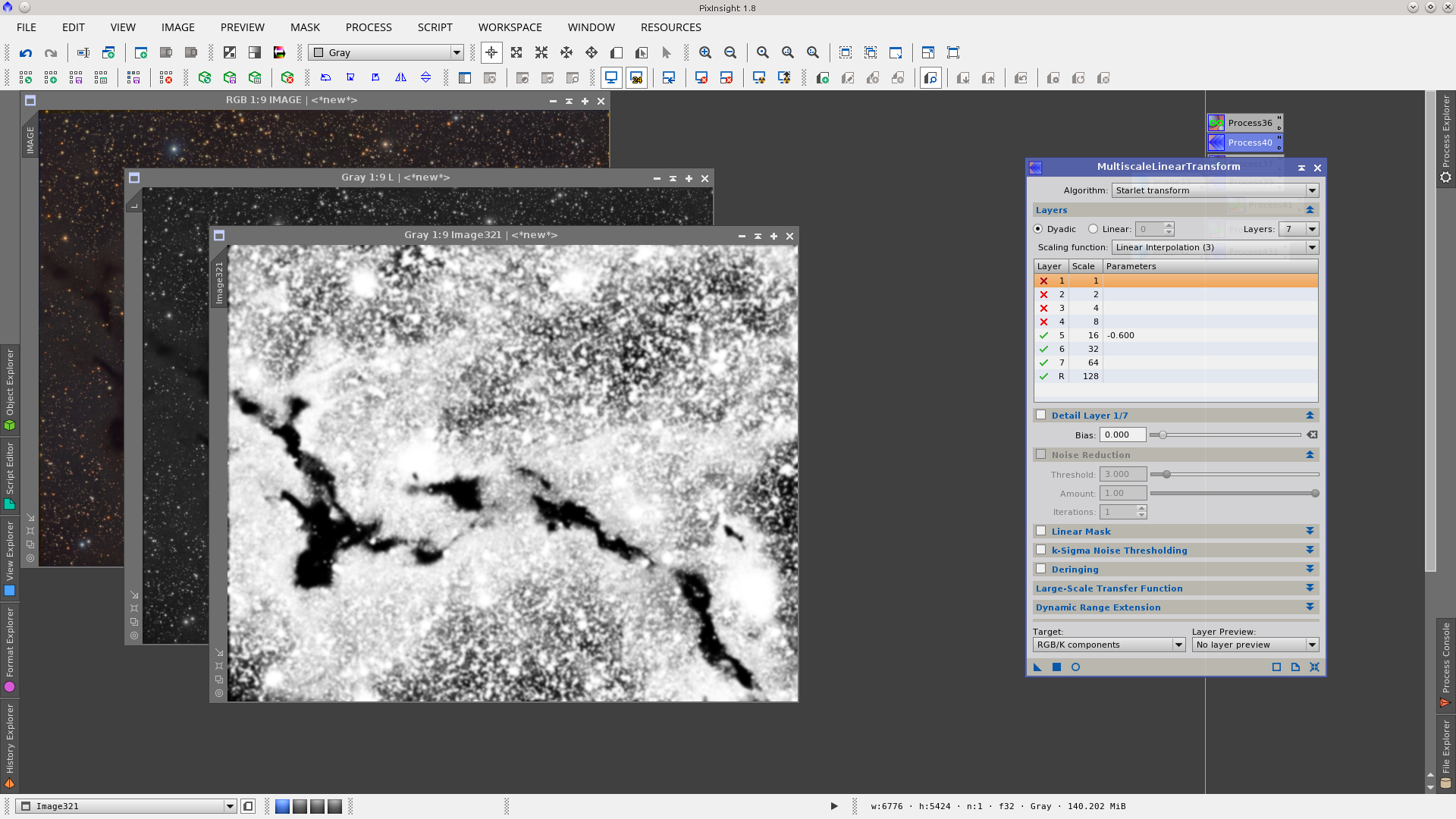
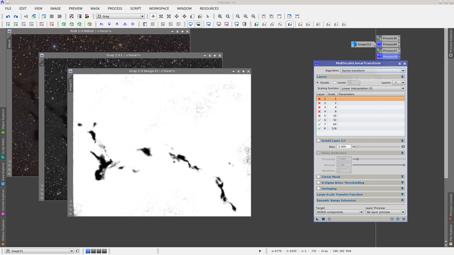
In this example I will use the MultiscaleLinearTransform tool to do the necessary smoothing of this first auxiliary mask. Note that I removed the layers from 1 to 4 and also reduced the Bias in layer 5. In this way the values of 0 and 1 in the binarized mask are smoothed to intermediate values.
The second step is to repeat the operation with the PixelMath tool but this time with a lower binarizing threshold value. In this way you will get a similar auxiliary mask but with another range of protection on the image.
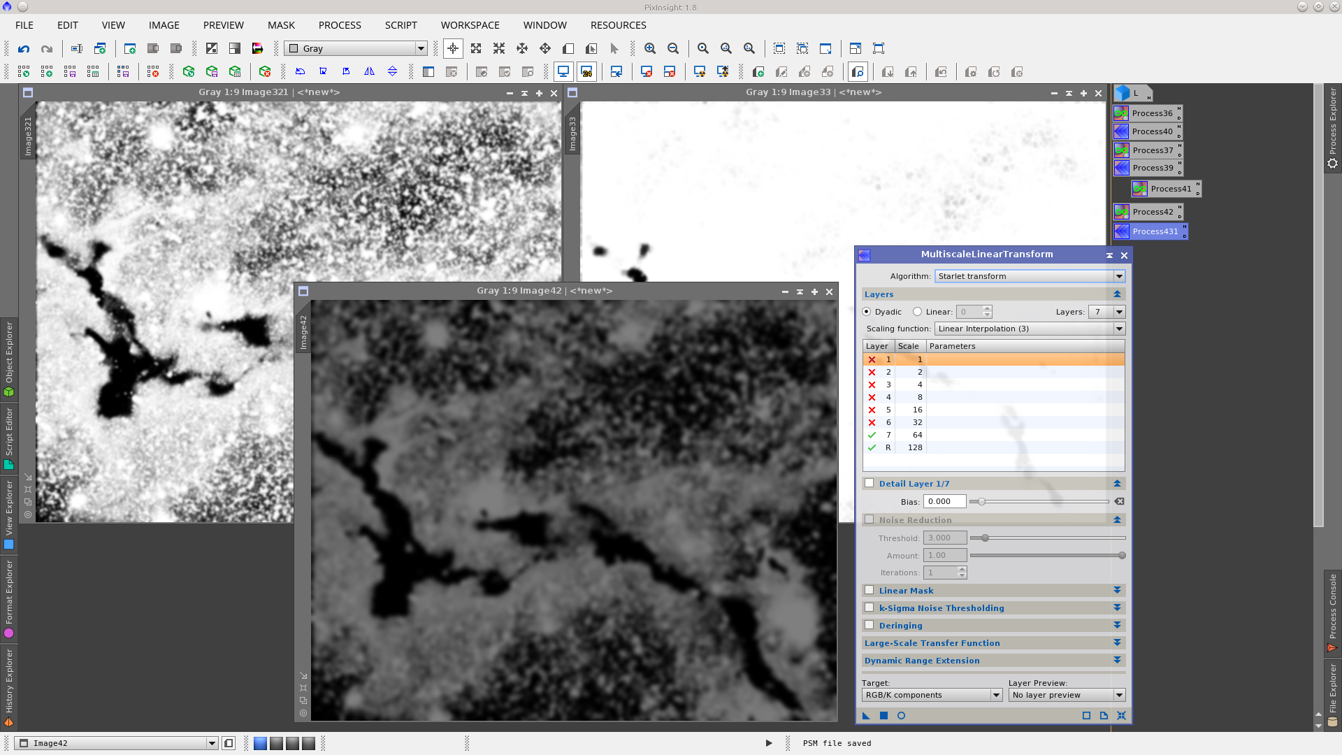
Once again we smooth the result using MultiscaleLinearTransform tool. Note that I remove the layers from 1 to 5. This smooths the binary values and results in partial mask protection in the transition.
Now we will operate with those two auxiliar masks in order to obtain a new one that represent the nebulosity where we want to apply intensity tranformations.
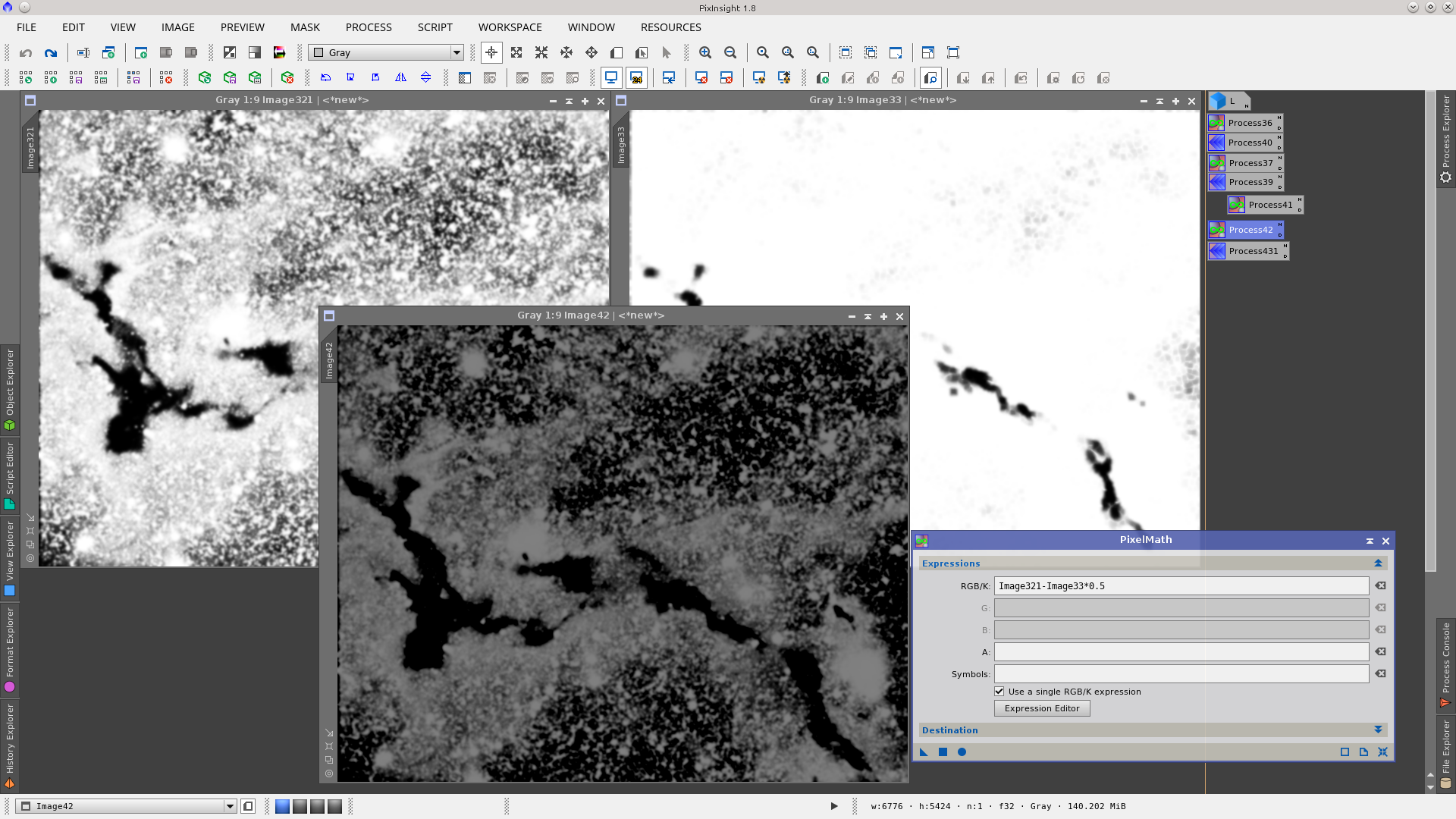
By subtracting 50% of one from the other we obtain the desired result.
Finaly we smooth again using the MultiscaleLinearTransform tool and the Lmask is ready to be used to protect the background and dark nebula while applying an Intensity transformation to the faint nebulosity. Typically a transformation can be applied to increase nebulosity while protecting the background, then the Lmask may be inverted to apply another transformation to decrease the background while protecting the nebula.
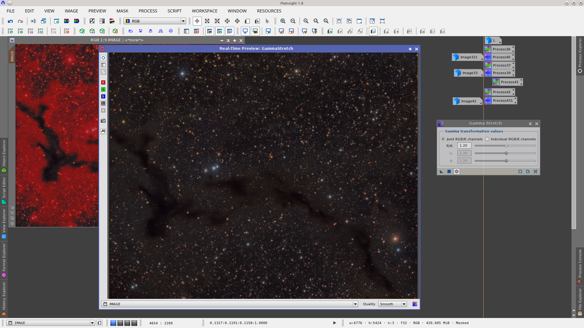
My tool of choise in this example was the GammaStretch tool. First protecting the soft nebula decreased the value of background brightness
Now invert the mask and apply the opposite transformation. This increases the brightness of the nebula while the mask protects the background
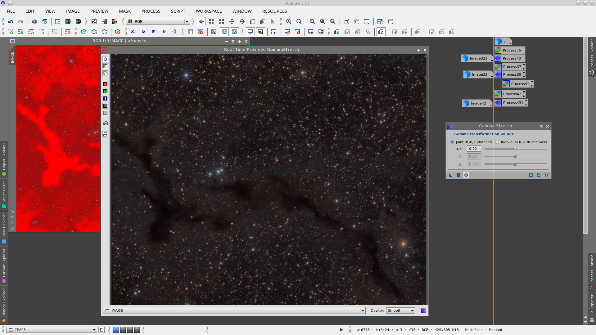
See the next screenshot for the final Before and After GammaStretch using the Lmask.

StarMask with StarMask tool
The StarMask module is located in Process > MaskGeneration > StarMask
You can generate a star mask by applying the default values of the StarMask process to a linear image, but it may be necessary to fine tune some parameters in order to adjust the result. In general, big stars on a linear image are not included by using the default parameters of the process. You can adjust that by increasing the Scale value. Higher values of Scale will include larger structures in the generated star mask.
Let’s start by applying default values in the StarMask process on a linear image:
Increase the Scale parameter to increase the protection of big stars. You will notice that the radius of big stars increased while in the rest remained constant:
The Structure Growth section in the StarMask tool allows you to control the protection of large and small structures in the mask. In this example, if we need to extend the area of protection only on the largest stars we must increase the Large-scale parameter which applies mask protection to larger regions in the image. We can reduce the protection of small stars by decreasing the Compensation value, or even setting it to zero.
Further processing of the mask can also be done within the StarMask module. If you need to increase the protection (higher values in the 0-1 range) you can use Truncation. Decreasing this value improves protection in the cores of the masked structures. Values of 0.5 to 0.3 are enough to provide good protection of big star cores.
Some situations such as the use of deconvolution may require full protection of the saturated cores in big stars. (Saturation of stars cores can be avoided by performing a High Dynamic Range (HDR) integration.) Decreasing Truncation values even more you can reach pixel values approaching 1 and get full protection in those areas.
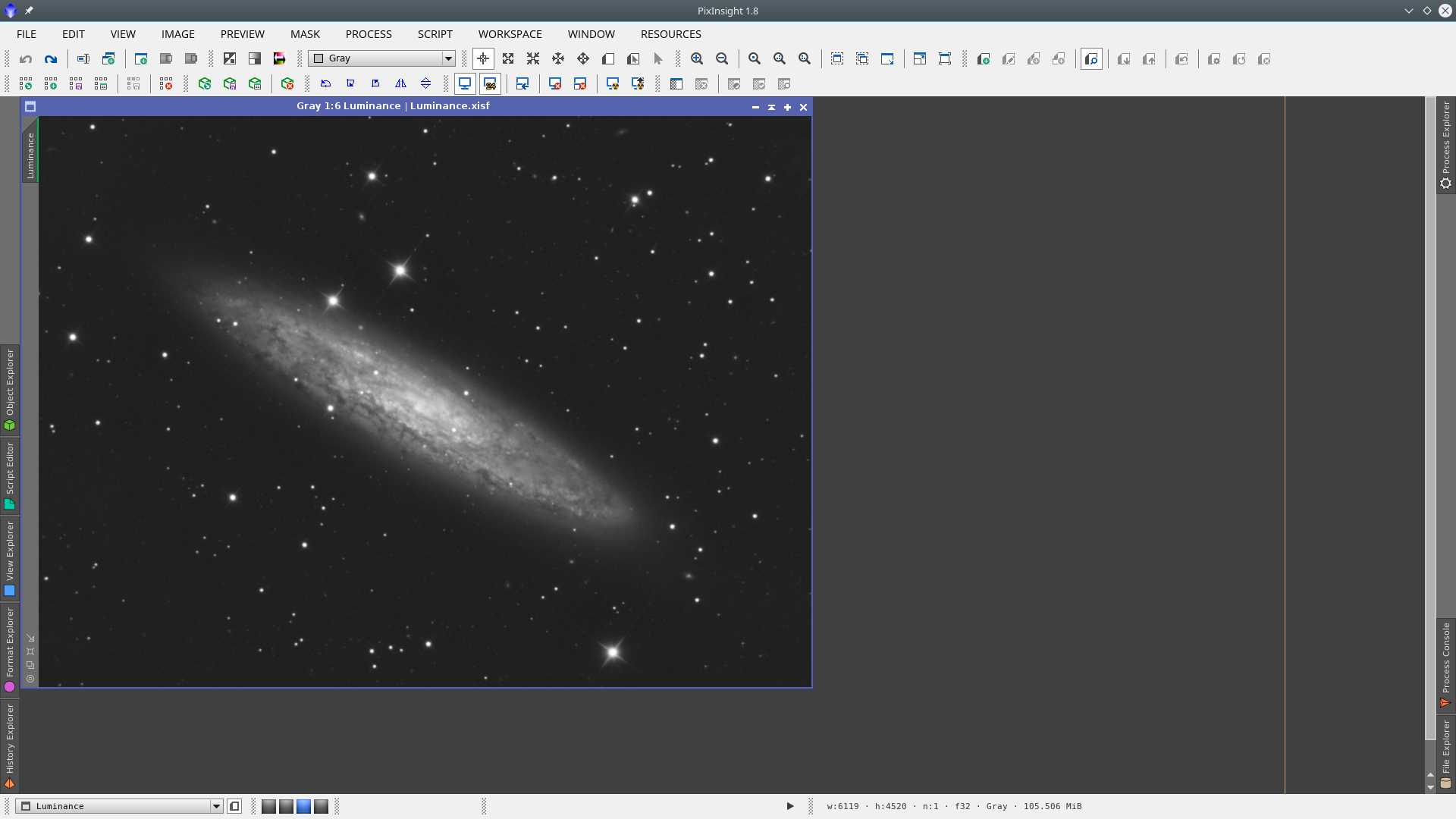
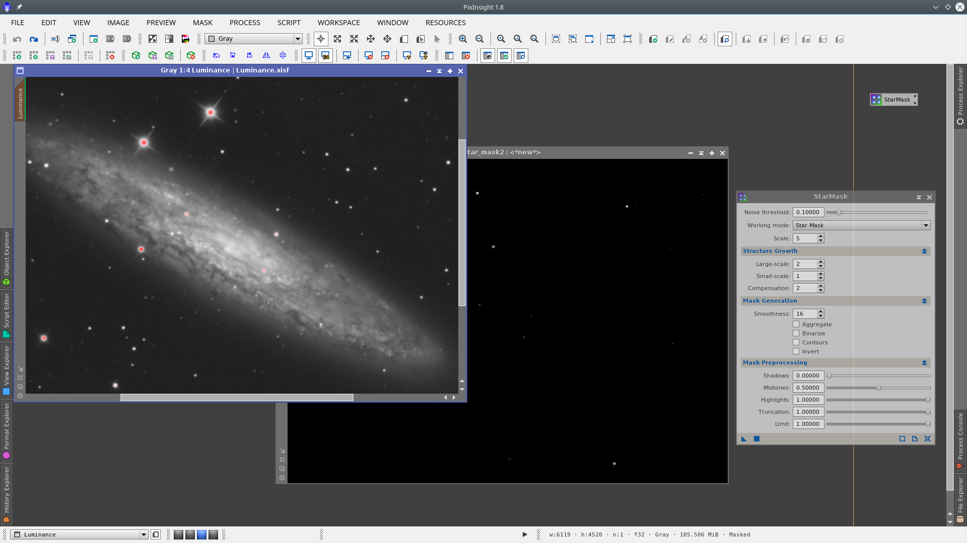
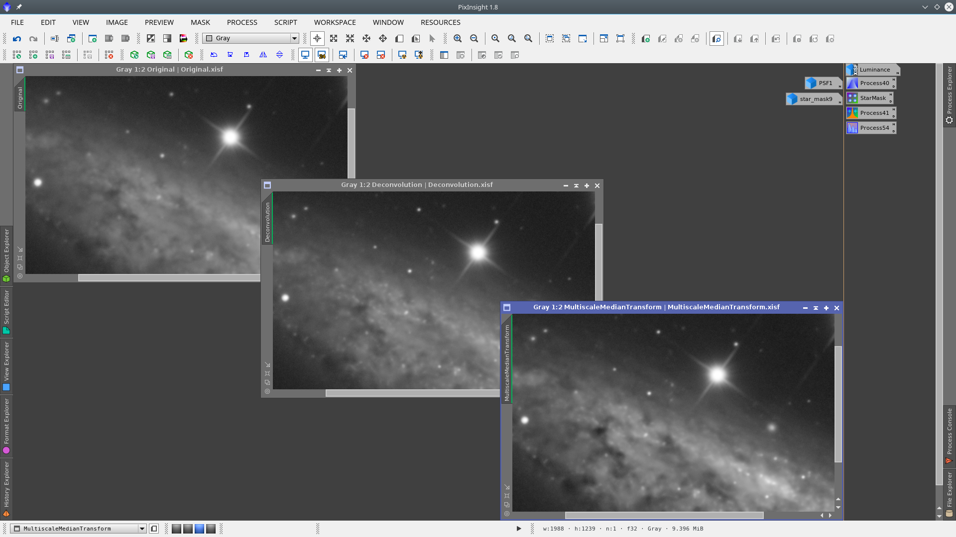
Let’s analyze the generation of a StarMask over the following image of NGC 253. This is also a linear image that has some very big stars, so our objective will be to protect those stars with an adequate mask during the Deconvolution and MultiscaleMedianTransform processes. Note that I will work with the STF activated to visualize the image. You can always identify whether the STF is activated or not by checking if the green identification line is present on the margin of the image identifier tab.
First apply the StarMask process with the default values. The generated image will give us a first idea of how StarMask process values should be modified in order to adjust the mask as required.
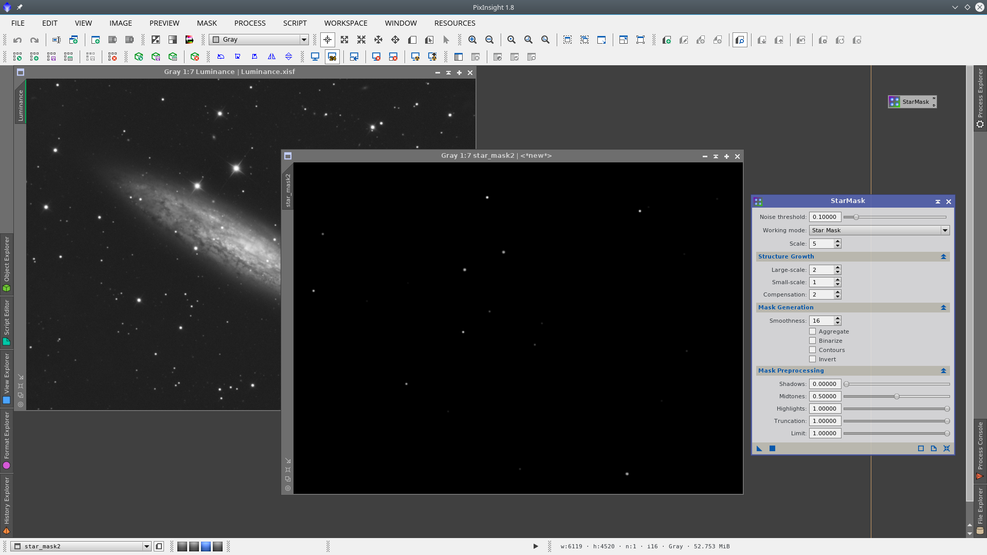
In this mask we have to analyze if the stars we want are there. In our example we look for the big and medium size stars, which are the ones that could be affected when applying deconvolution on the image. Note that those stars are included but they seem to still be small.
You can easily visualize the coverage of the mask by applying it on the image.
So the first logical change to do in the StarMask tool parameters is to increase the growth of large structures in the image. This modification will directly affect the diameter of the stars in the star mask. Note that I have increased it considerably, as the big stars always have big halos which I also want to protect, since in this example I will also give contrast to the galaxy using the MultiscaleMedianTransform tool.
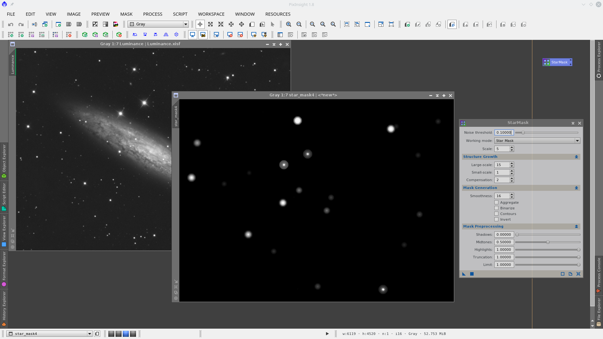
Now we have the desired radius for protection but the main two stars of the image don’t have enough protection for their halos. Increasing the Scale parameter we will obtain the desired protection of those stars.
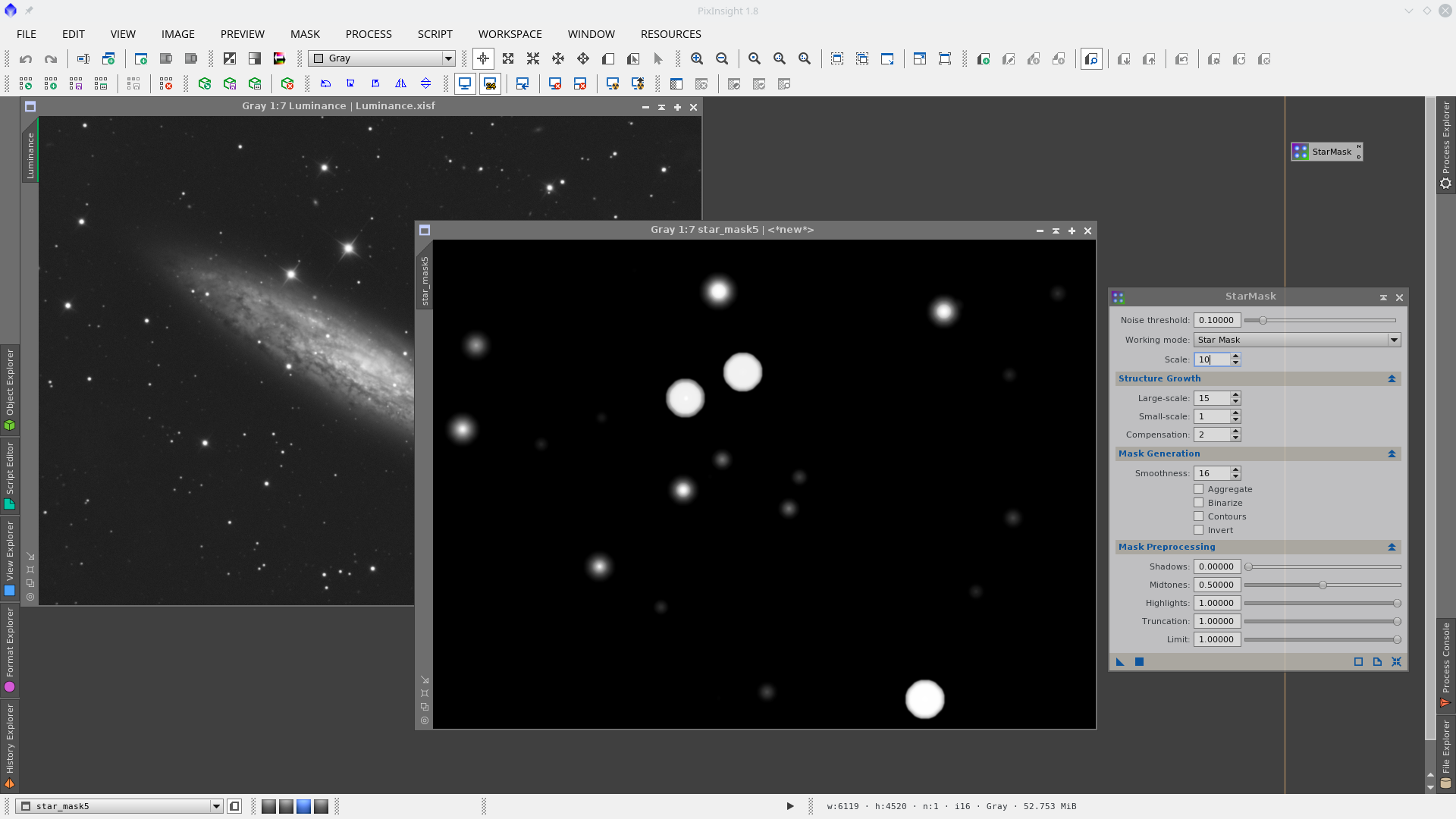
See how increasing of the Scale affects the radius and protection of big stars when the growth parameter has been previously increased:

The desired stars in the image will be now very well protected by the star mask for the subsequent application of Deconvolution and MultiscaleMedianTransform.
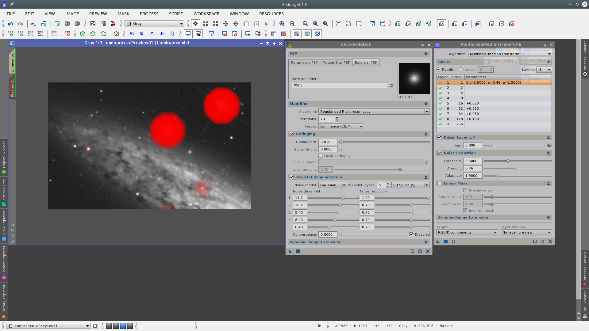
Finally see the sequence after applying both processes, protecting the stars with the star mask. Note that the critical stars have remained absolutely invariant.
You can also perform a star reduction on the big stars using the inverted star mask. In the next animation you can see the blink between the original image with no processes applied and the final image. In the final image Deconvolution and MultiscaleMedianTransform were applied while protecting the stars, and MorphologicalTransformation and NoiseGeneration while protecting the galaxy.
Let’s see another example of a star mask, applying the default values of the StarMask process, but this time over a non linear image.
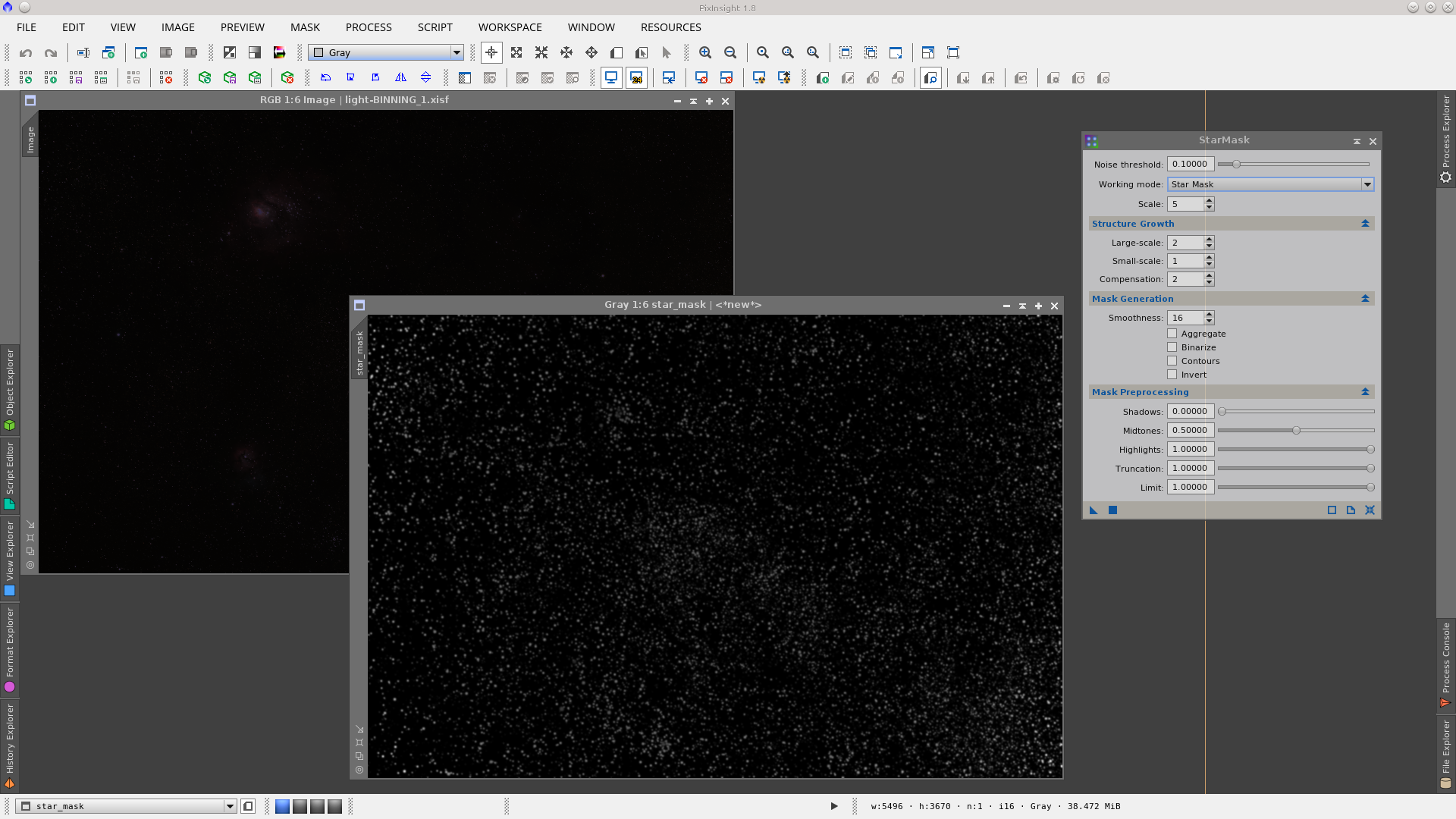
Again we start with the default values in the StarMask process:
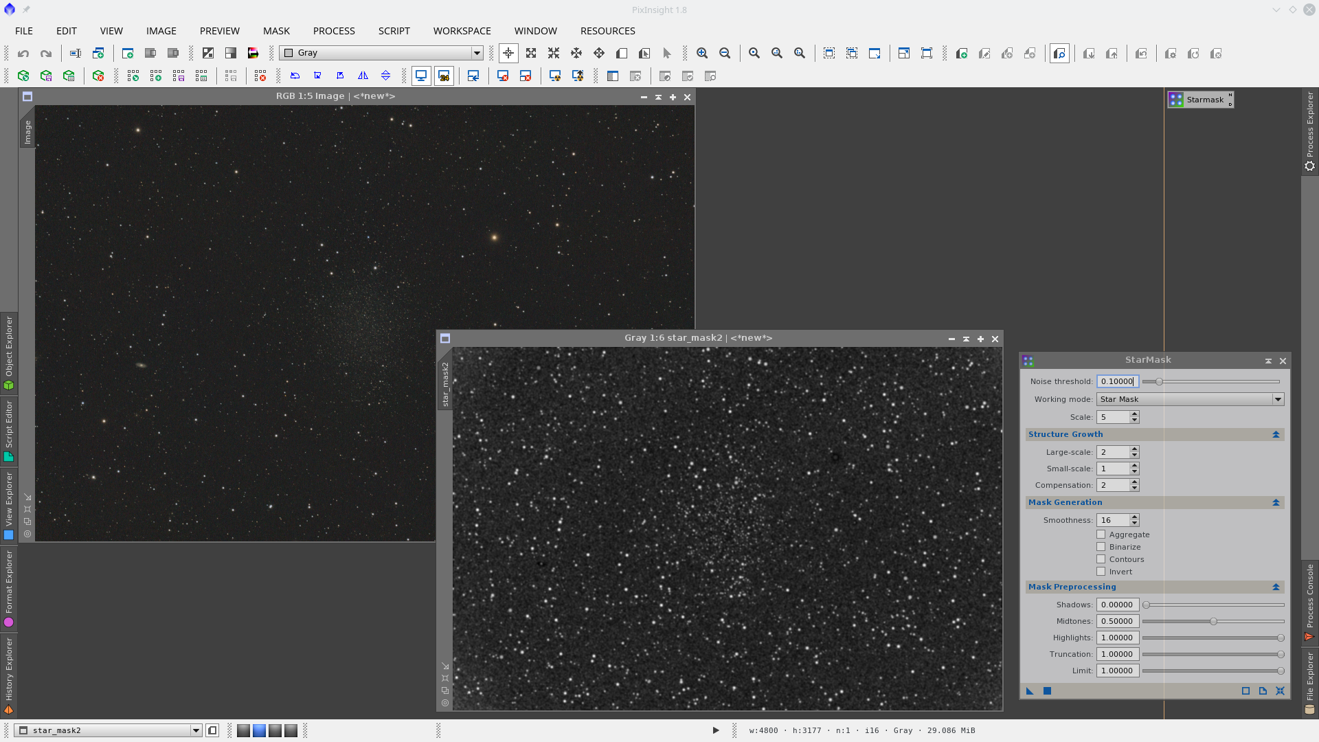
The default Noise Threshold parameter of the StarMask process generates a mask from this image with a lot of background detected as stars. So the first action will be to adjust this parameter. You have to increase the value in order to prevent including noise and fine tune it to adjust the result, checking that the detected stars in the mask are really stars and not noise.
Adjusted Noise Threshold values in the StarMask process on a non linear image:
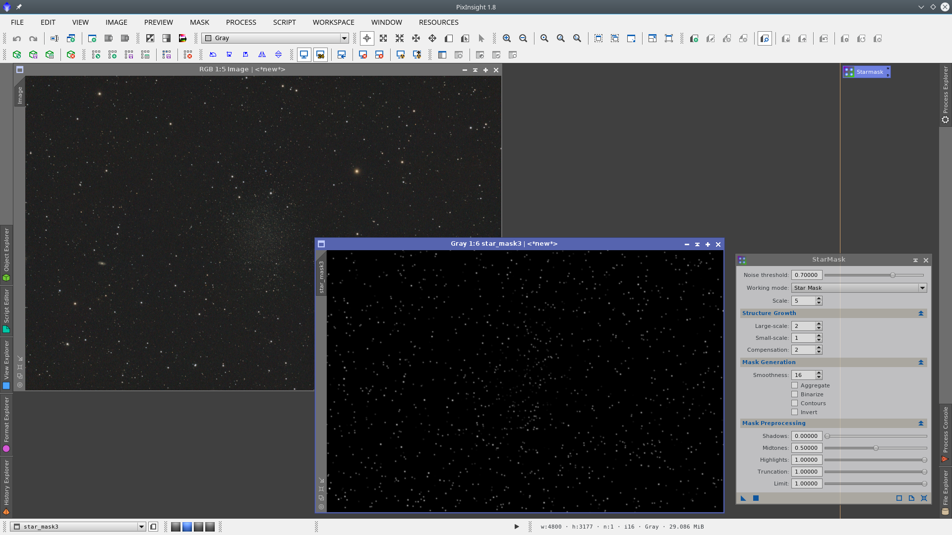
In general big stars on non linear images are not included when the default Scale parameters are used, and they have to be adjusted. Higher values of Scale include larger structures in the generated star mask.

See before and after increasing the Scale parameter on the StarMask tool:
Now, these parameters of the StarMask tool provide the protection I was looking for on this image.
HaloMask
A HaloMask is a mask intended to isolate the halos of the stars with the goal of doing some work on them. Generally we look for reducing the halos present on big stars.
HaloMask with StarMask tool on linear images
A simple and quick HaloMask can be made with the StarMask Process, which is located in Process > MaskGeneration > StarMask.
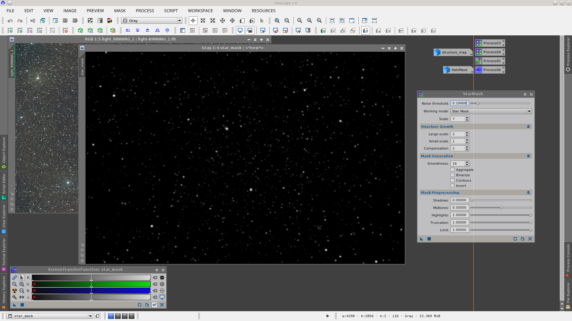
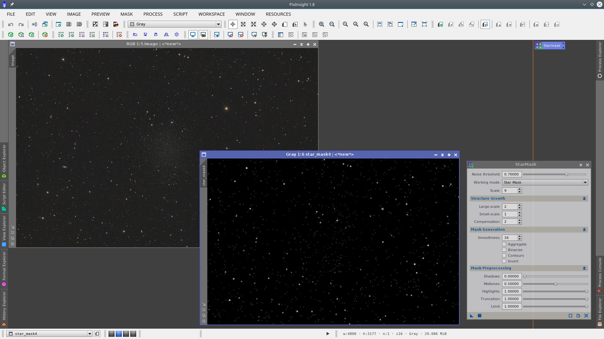
You can apply the StarMask tool on a linear image with appropriate values to include medium and large stars. It may be necesary to fine tune some parameters in order to adjust the result. In general big stars on a linear image are not included with the default parameters of the process, but this can be adjusted by increasing the Scale value in the StarMask tool. The larger values of Scale will include the largest structures in the generated star mask.
In this example I have only increased the Scale parameter to include the biggest stars of the image. You may want to lower the Noise Threshold parameter to include more stars in your mask.
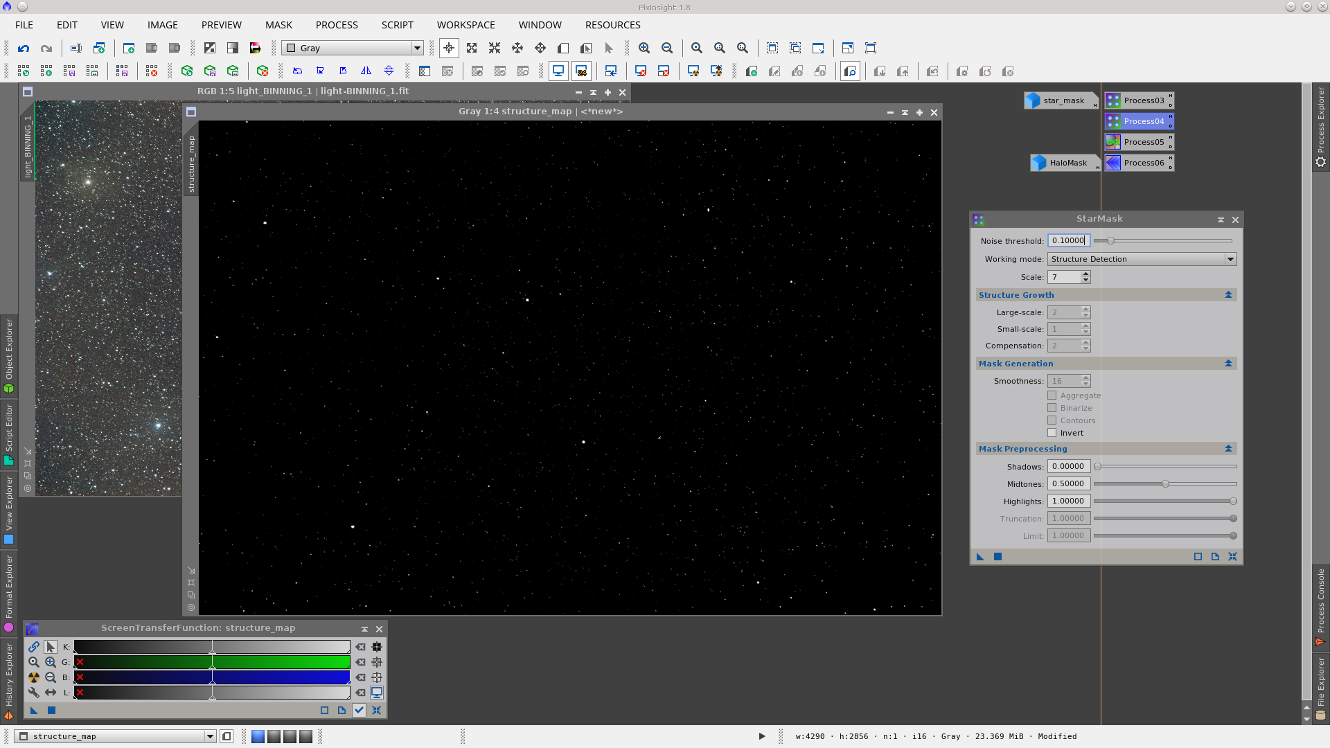
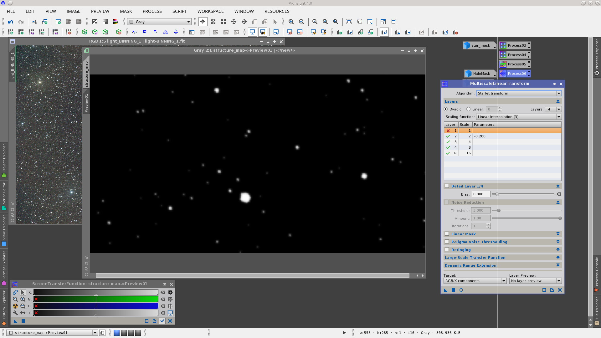
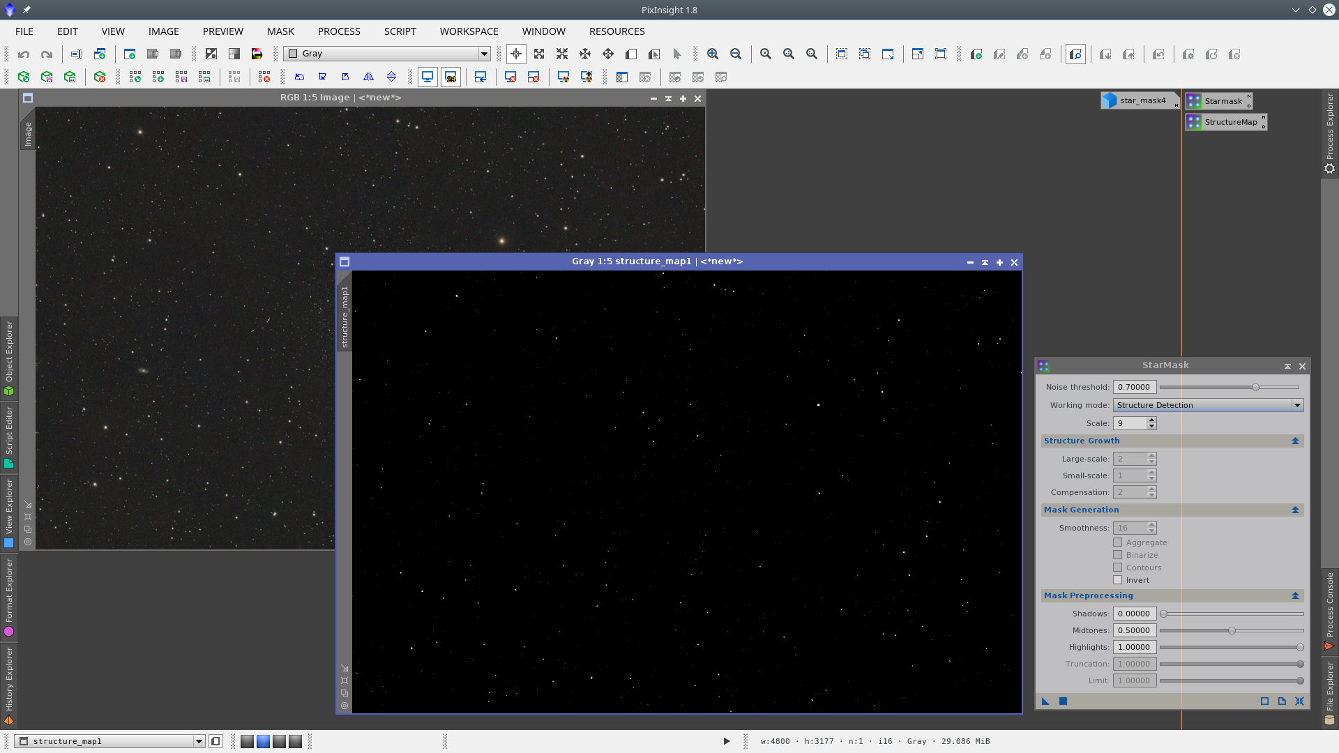
The second step is to change the Working Mode to "Structure Detection" and apply it to generate the structure_map image.
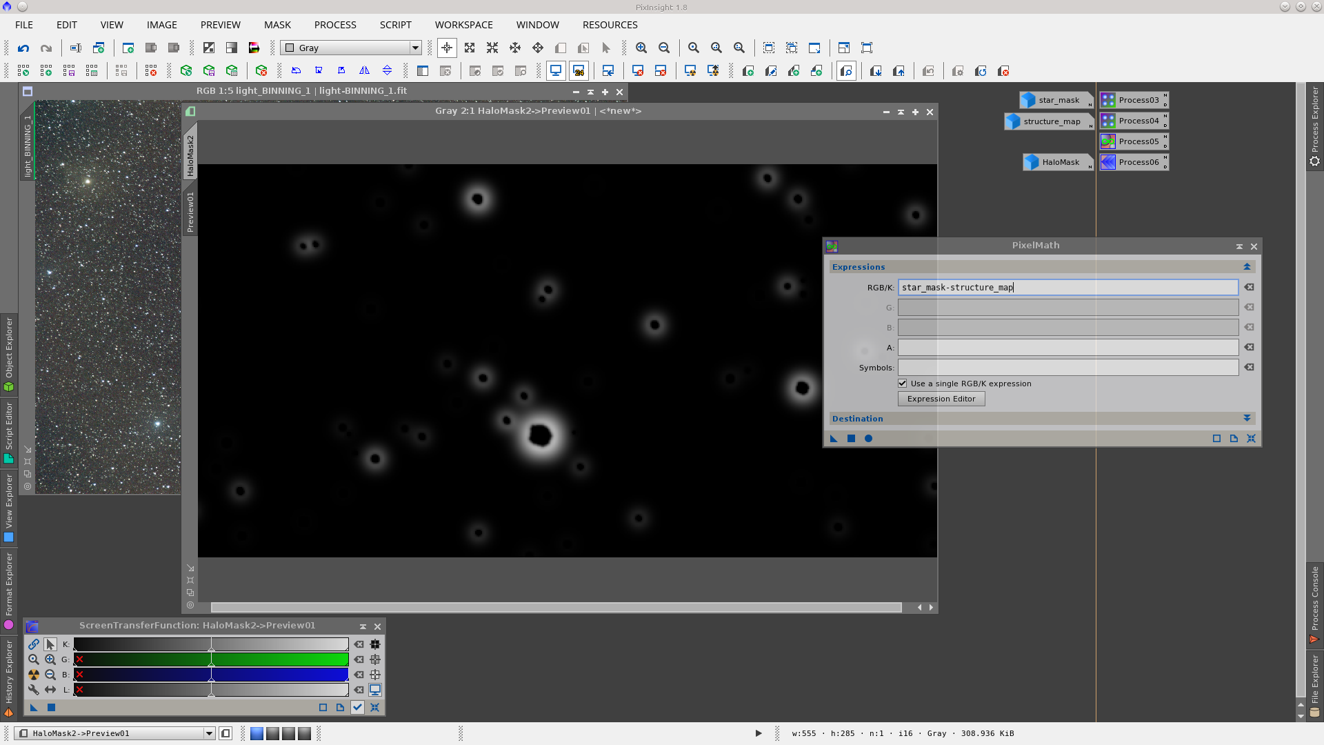
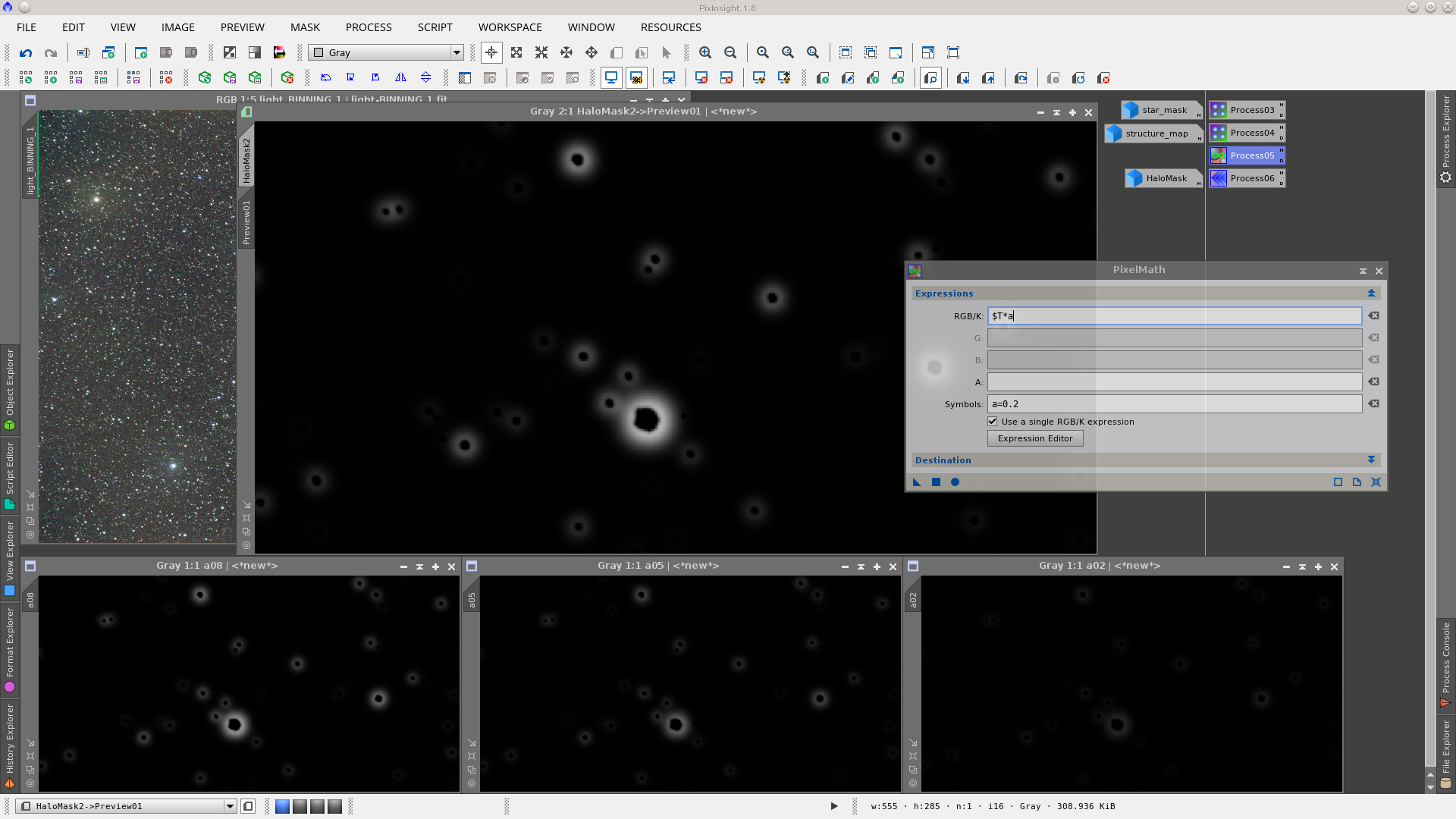
The difference of these two images (star_mask - structure_map) will generate a HaloMask. Using the PixelMath tool, write that expression in RGB/K.
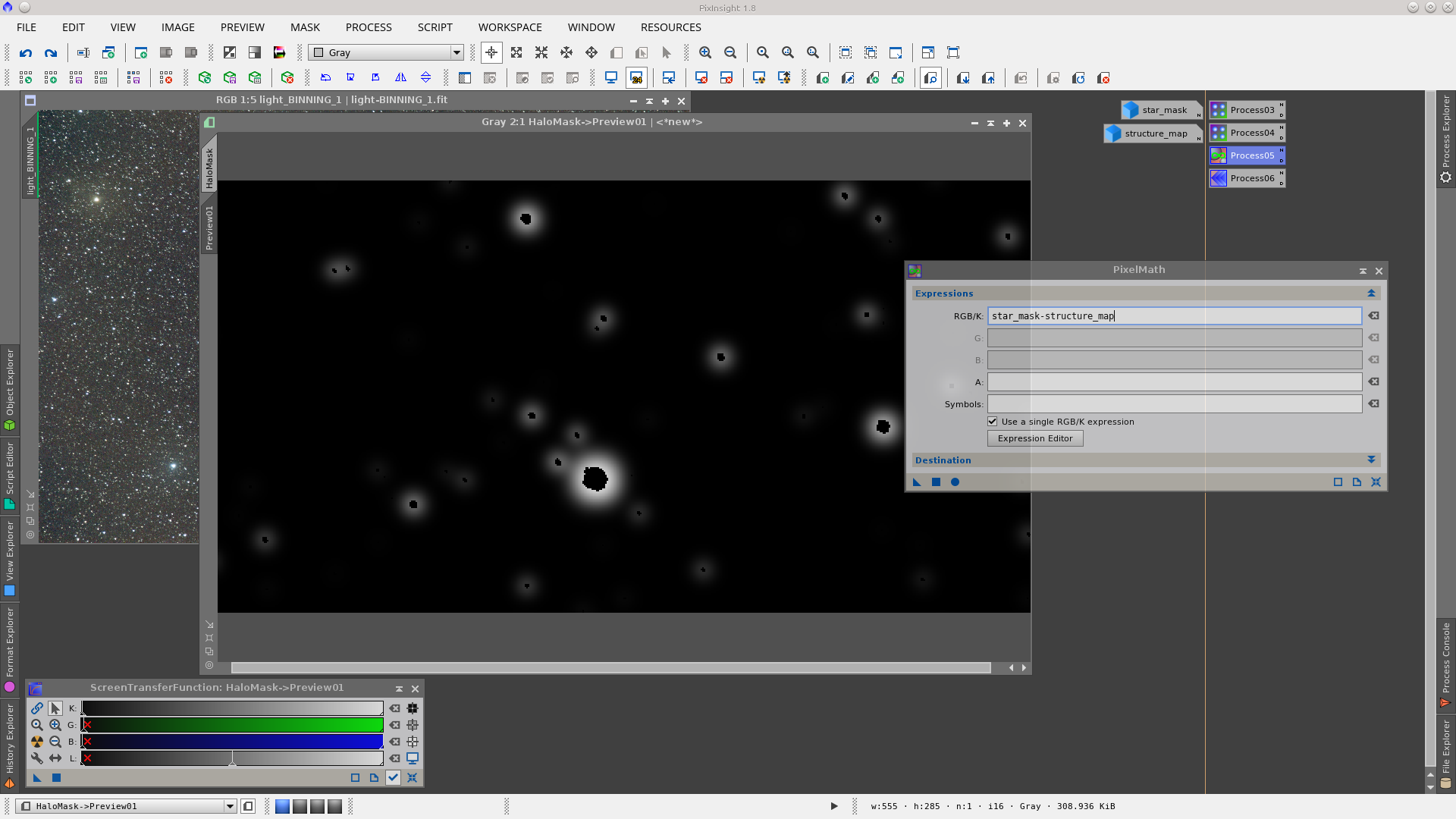
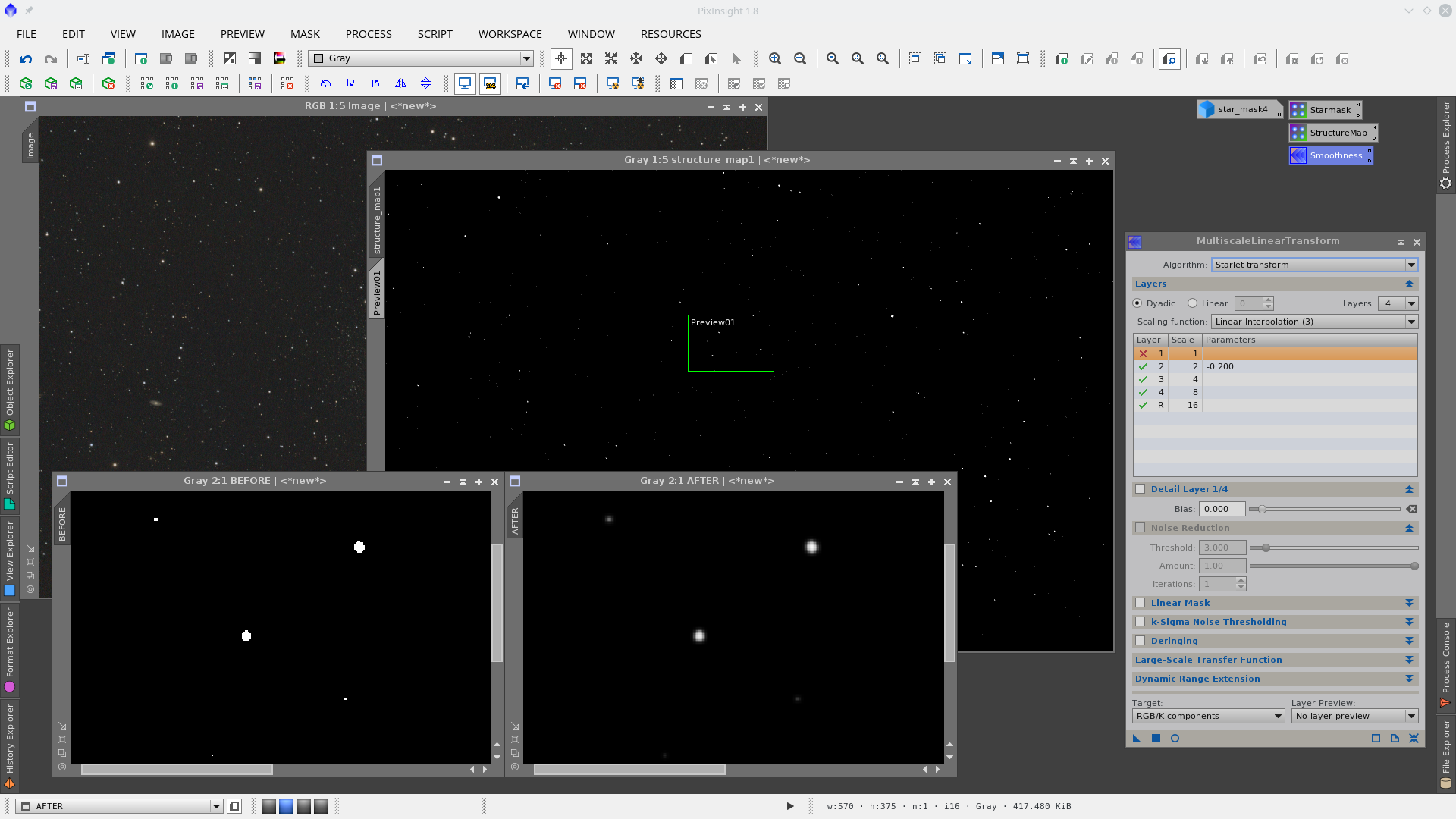
In most cases, depending on the images and situation, the structure_map, which is a binarized image, will need some processing to smooth the edges of the star cores. This processing can be done before or after the subtraction of the mask with different results. The tool of choice to perform the smoothing in this example was MultiscaleLinearTransformation where I have deleted the one-pixel layer and decreased the Bias value slightly in the two-pixel layer.
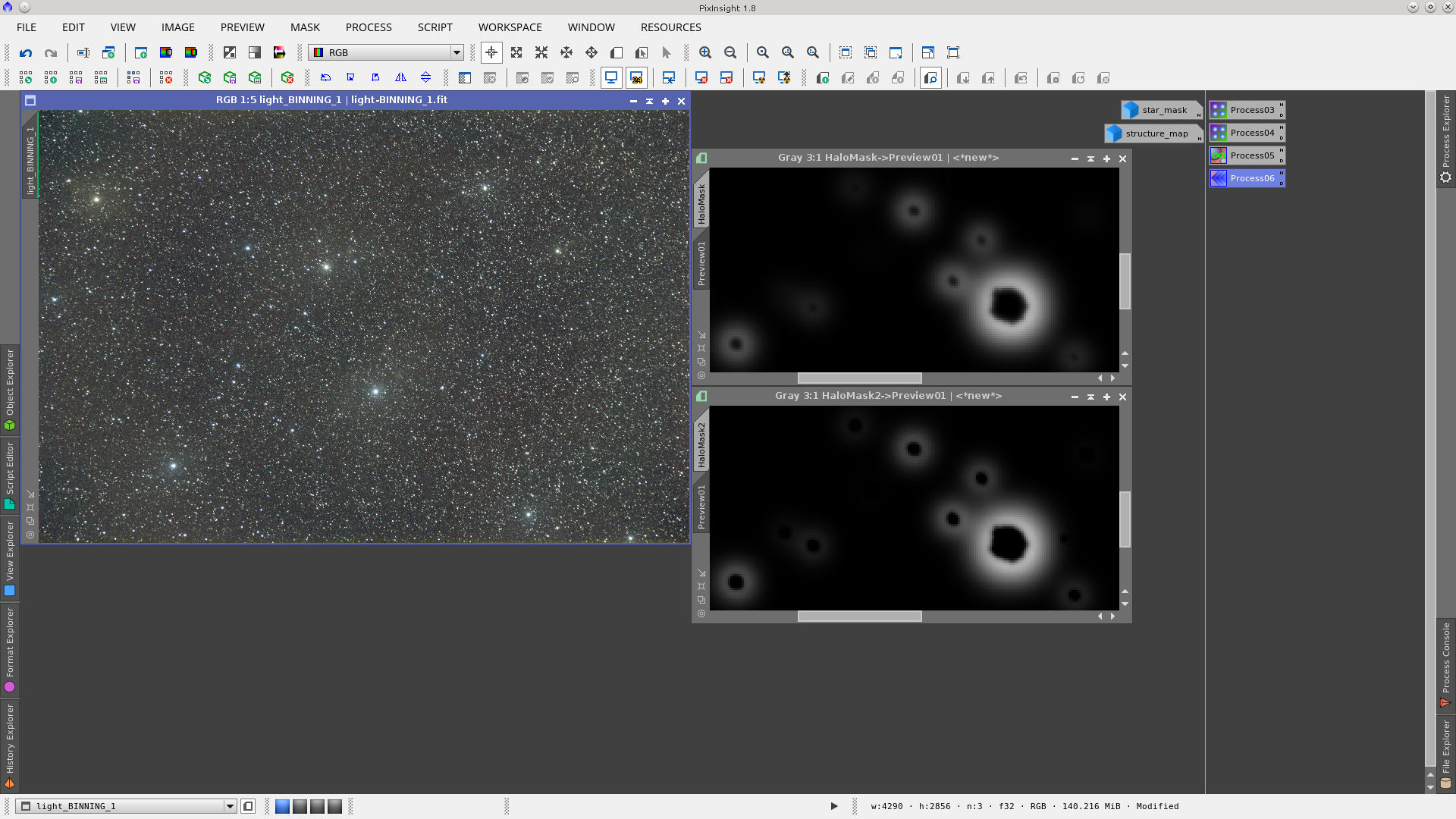
Let's see both situations:
Smoothness may be applied directly on the generated HaloMask, that is, after the structure_map image was subtracted from the star_mask image.
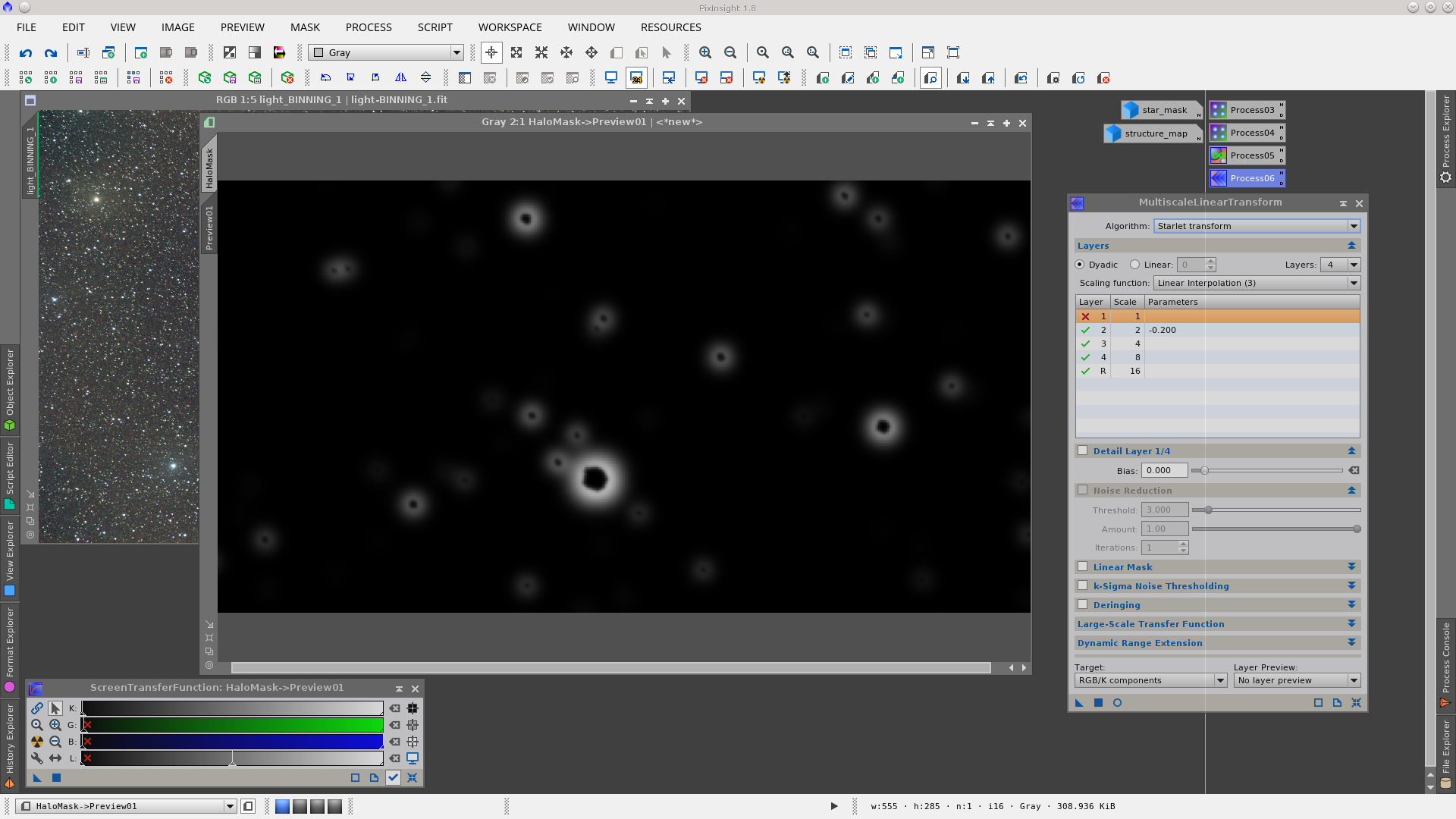
Or smoothness may be applied to the structure_map before it is used to generate the HaloMask.
And now subtracting:
Note that the parameters applied to MultiscaleLinearTransformation were the same in both cases but the result is slightly different in the amount of protection that the mask will provide to the star cores.
To increase halo protection, you can multiply the result by a factor. You may need to try different values of that factor in order to have a correct HaloMask.
If the image is a non linear image (for example it was already stretched with the HistogramTransformation tool) the default parameters of the StarMask process will give a very different result to the ones obtained in the linear stage of the image. A halo mask made in this stage of the image processing will need more tuning of the parameters to achieve similar results.
HaloMask with StarMask tool on non linear images
Let’s see a second example of a HaloMask, following the same procedure as before but with a stretched image. This image has been processed through the linear stage and the MaskedStretch tool has been applied for the non linear transformation.
On this non linear image we will apply the StarMask tool using appropriate values with the goal of including medium and large stars. It may be necessary to fine tune some parameters in order to adjust the result. In general big stars in non linear images are not included using the default parameters of the process, so the Scale value in the StarMask tool will need to be increased to include those stars. Larger values of Scale will include larger structures in the generated star mask.
Note: increasing the Scale may also include non stellar objects like the cores of the galaxies.
In this example of a non linear image I have also increased the Noise Threshold parameter to avoid including noise in the mask.
Generate the starmask:
Now change the "Working Mode" to "Structure Detection" in the StarMask tool to generate the structure_map image:
Apply smoothness on the structure_map image using the MultiscaleLinearTransform tool with the objective of having a better transition between the star cores and the star halos. The structure_map image as generated is a binarized image with values of 0 (full protection) or 1 (no protection) and the smoothing process will fill in the transitions, values between 0 and 1. Note that in this example I have only deleted the one-pixel layer and set a negative value for the two-pixel layer which worked well enough, but you may need to fine tune these parameters.
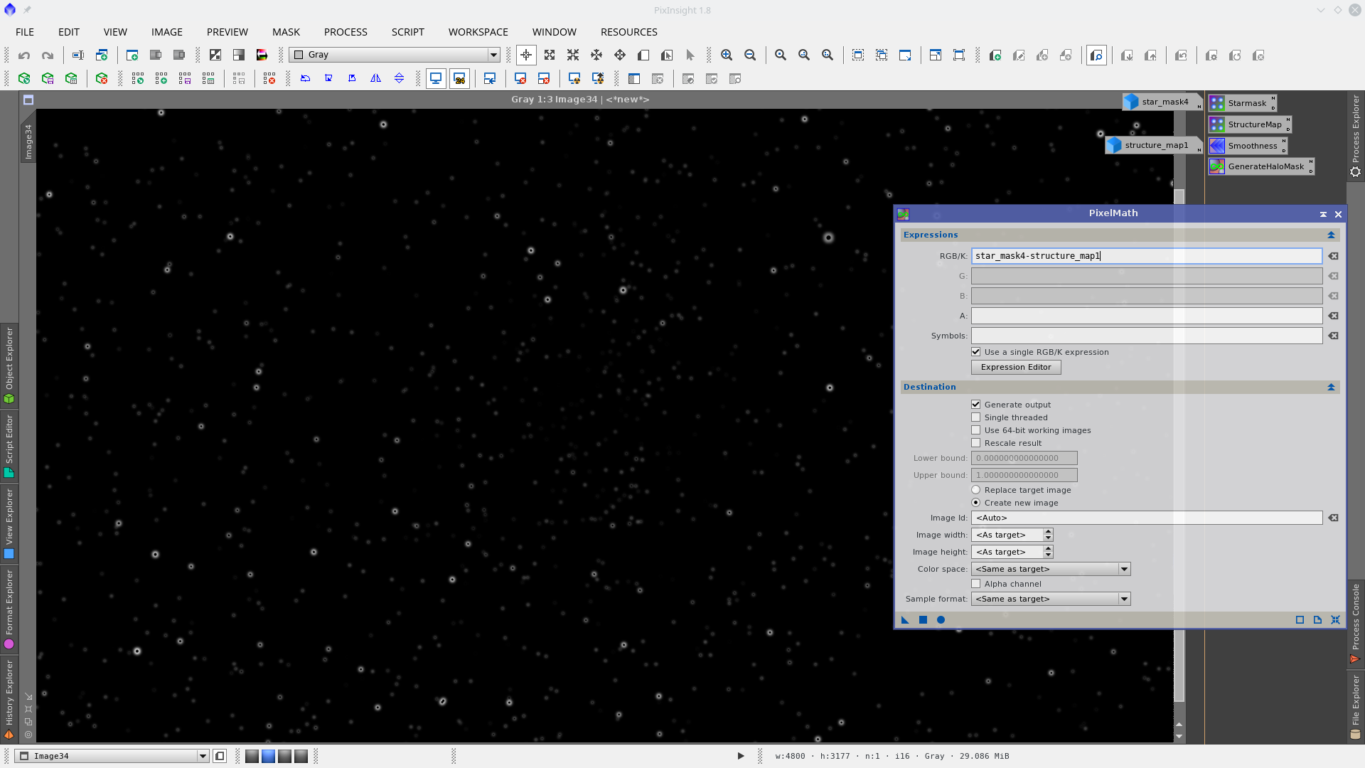
Finally apply the PixelMath process to generate the HaloMask. The difference of these two images will generate the mask. In the PixelMath tool write the expression (star_mask4 - structure_map1) in the RGB/K field and drag the blue triangle onto one of the images.
Note: the names of the images to be subtracted (star_mask4 and structure_map1) are particular to this example. You must change them to the names of the image you in your process.
Note: the PixelMath tool will generate a new image only if it has been set up in the tool. If not, the HaloMask will replace the target image.
Now with the HaloMask protecting the background of the image and the star centers, you can apply the MorphologicalTransformation tool (or other suitable process) to reduce the halos.
See Before and After star halo reduction: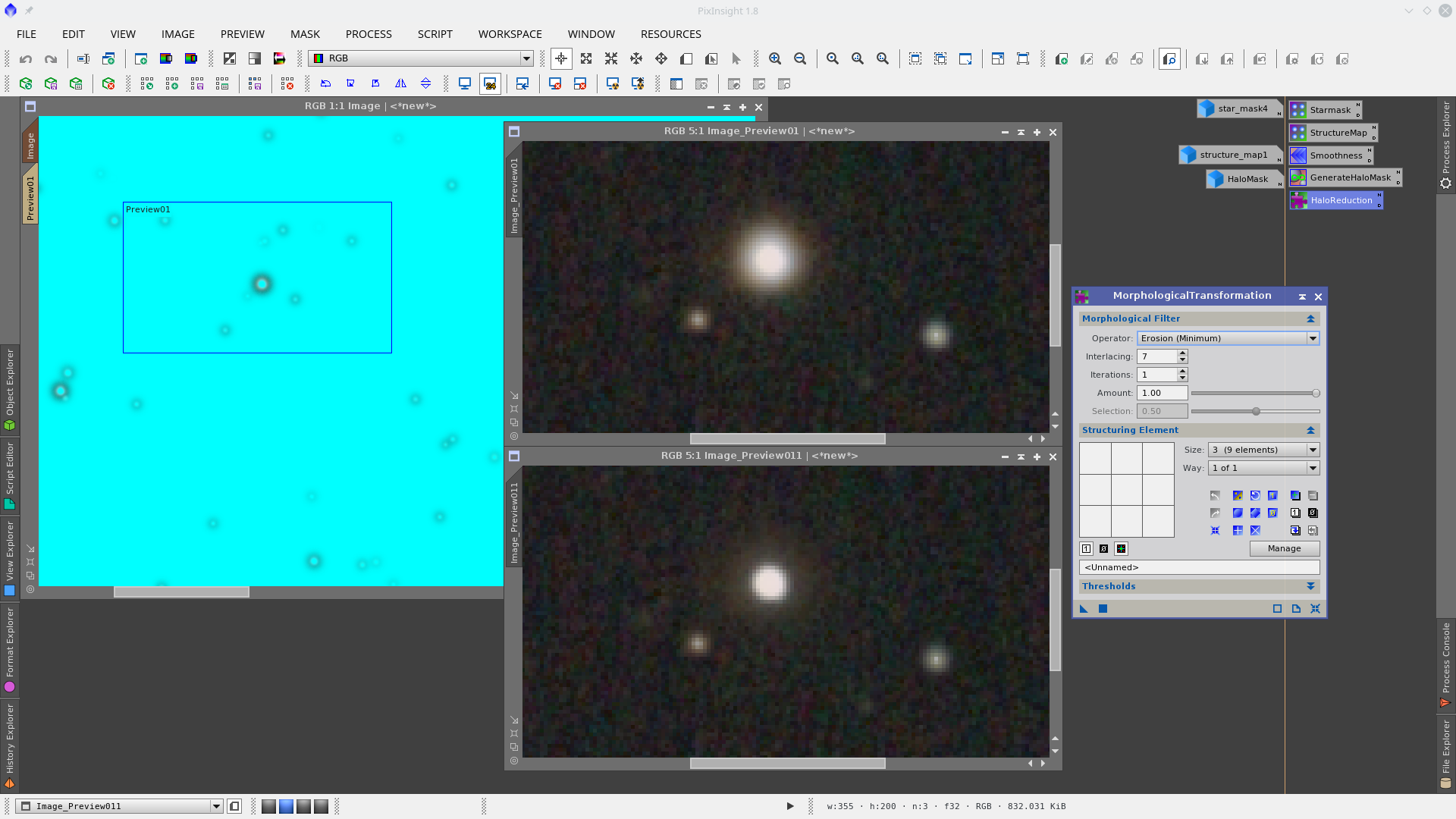
HaloMask with RangeSelection tool in non linear images
Let’s see another example of HaloMask. In this case the image has stars and a dark nebula, and we will use the RangeSelection tool instead of the StarMask tool to make the intermediate masks.
We are working here with a non linear image, in which TGVDenoise has been applied in chrominance and TGVImpaint has been used to correct the darkest pixels in the nebula.
The objective here is to work on the halos of big and medium size stars, generating a mask that can protect the stars cores at the same time as the nebula and background of the image.
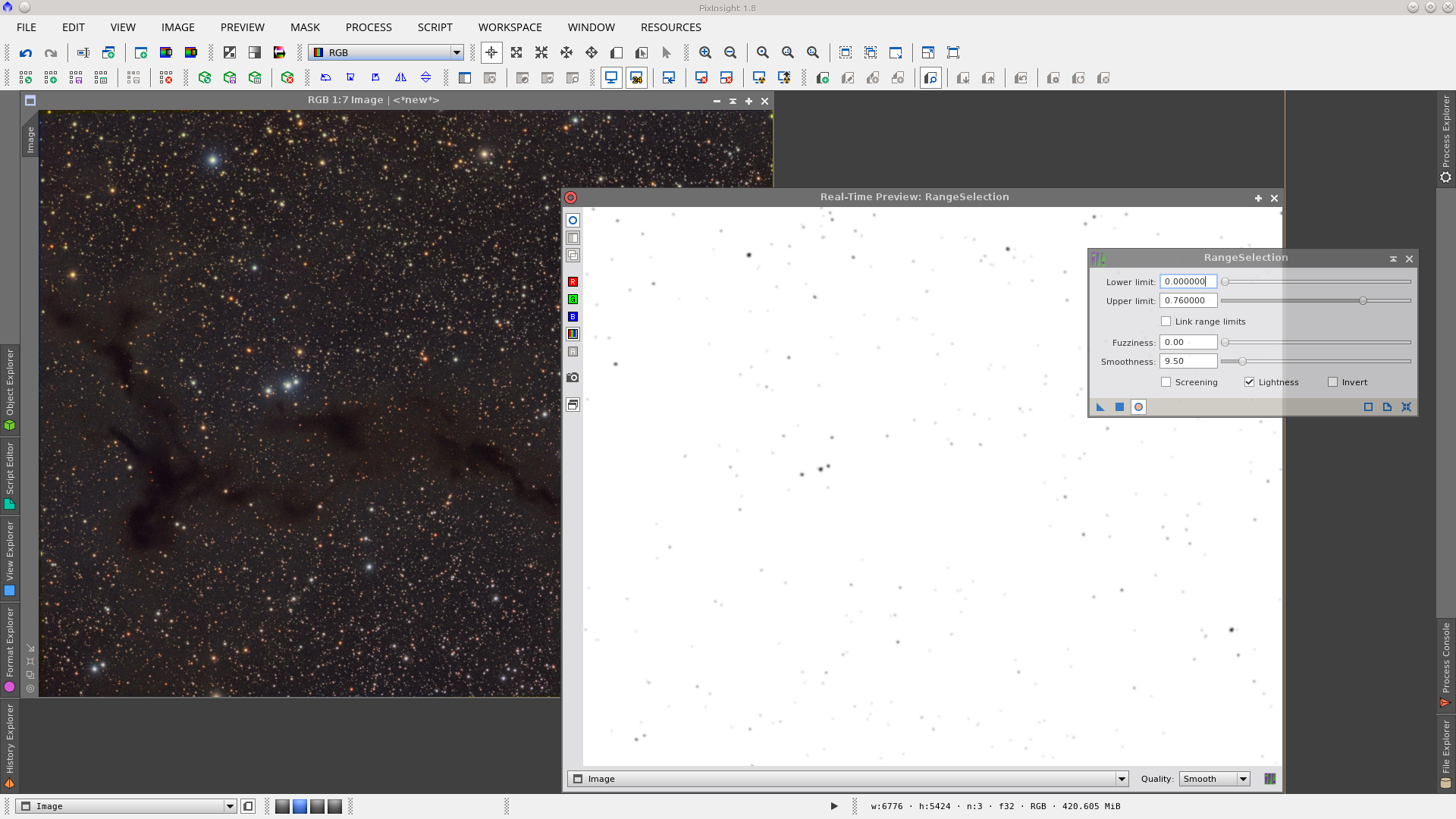
The first step is to open the RangeSelection tool and generate a range mask to represent the cores of the stars. Note that the Smoothness has been increased to have an adequate transition between the stars and the halos.
The next step is to increase the radius of the stars in the generated mask to reach the radius of the halos using the MorphologicalTransformation tool. I have chosen Erosion as the operator with a circular structure of 25 pixels, which gives the desired halo. This step may require some trial and error.
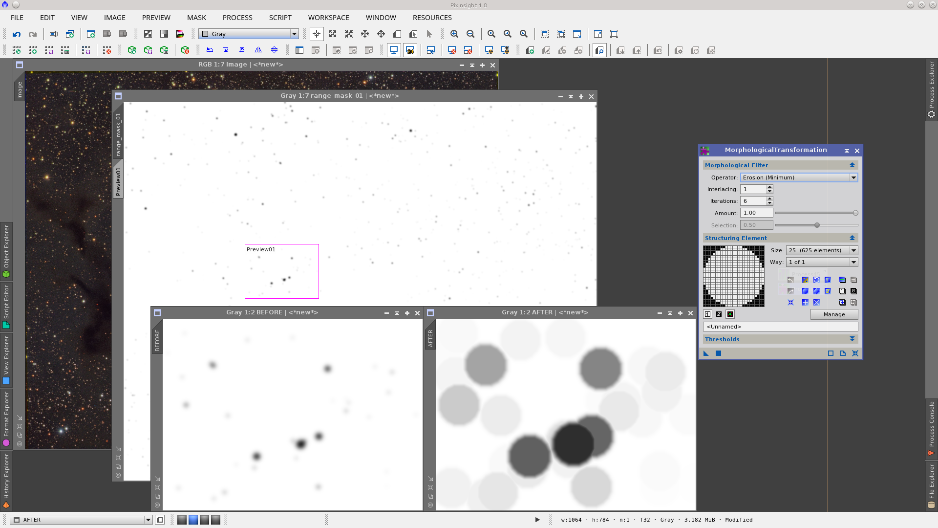
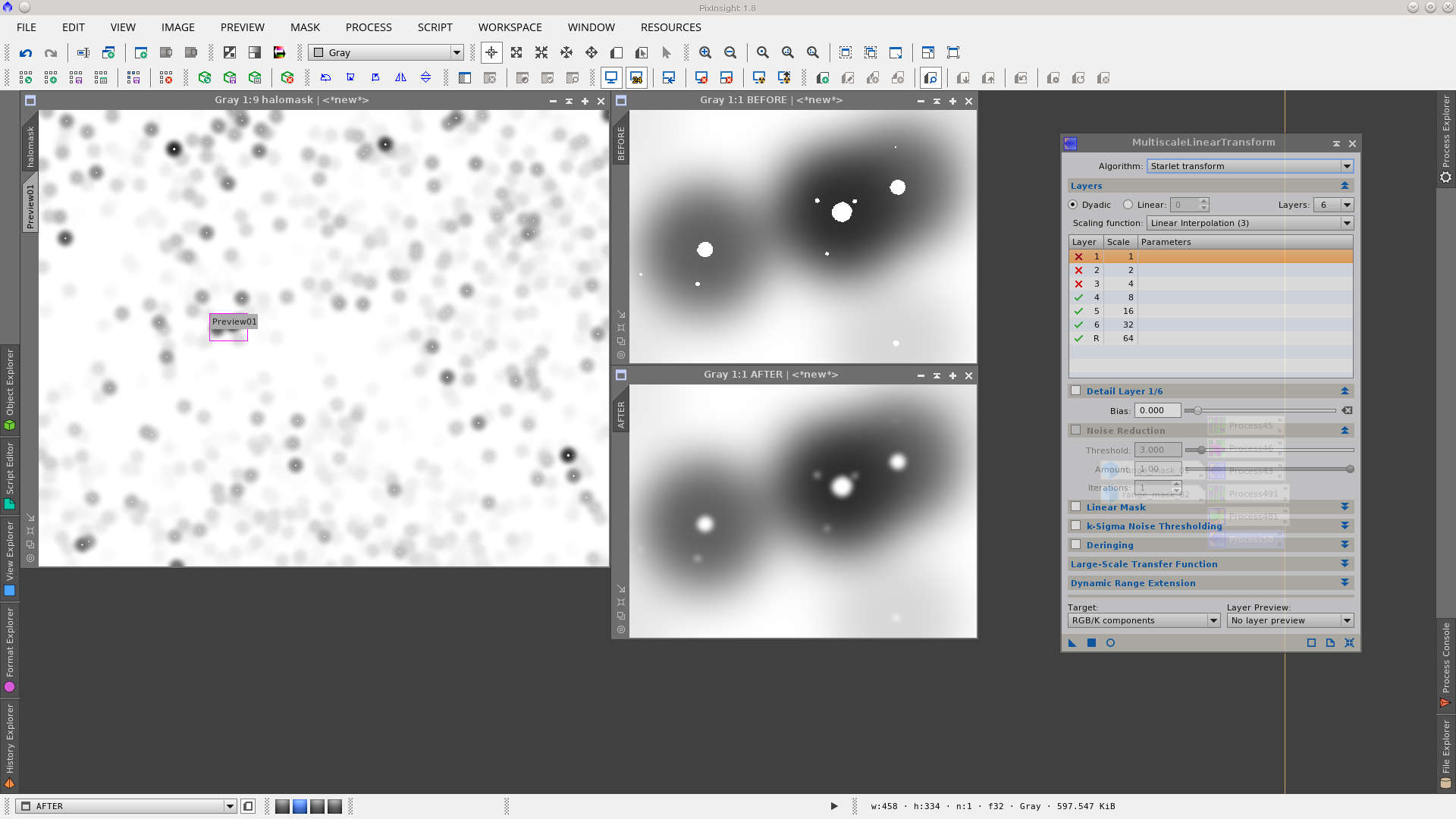
This representation of the halos needs to be smoothed, for which I used MultiscaleLinearTransform, deleting the six first layers.
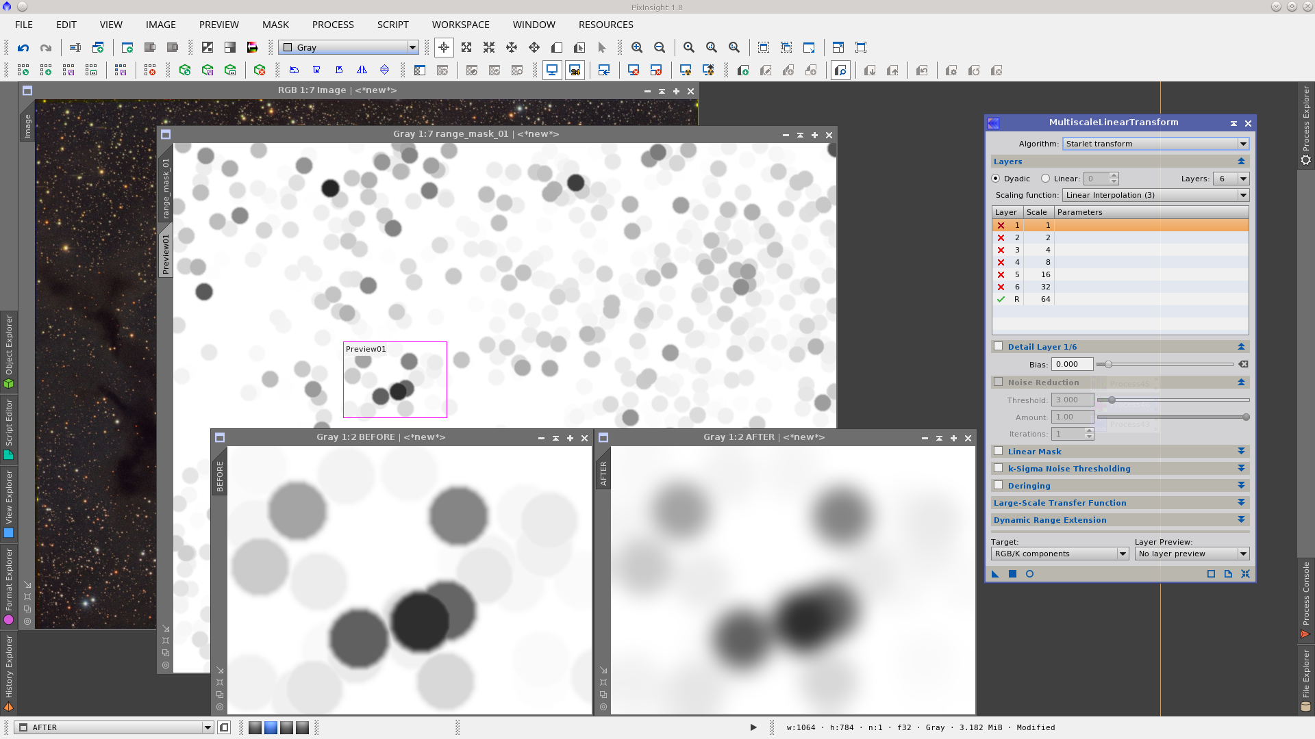
Once this first intermediate mask has been obtained, you may want to blink between it and the original image (CTRL+PageDown - Switch Images) to test that the radii in the mask are a good representation of the radii of the stars in the image.
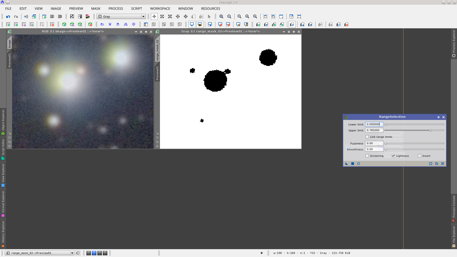
The next step will be to find a representation of the star cores. The tool of choice is also the RangeSelection tool.
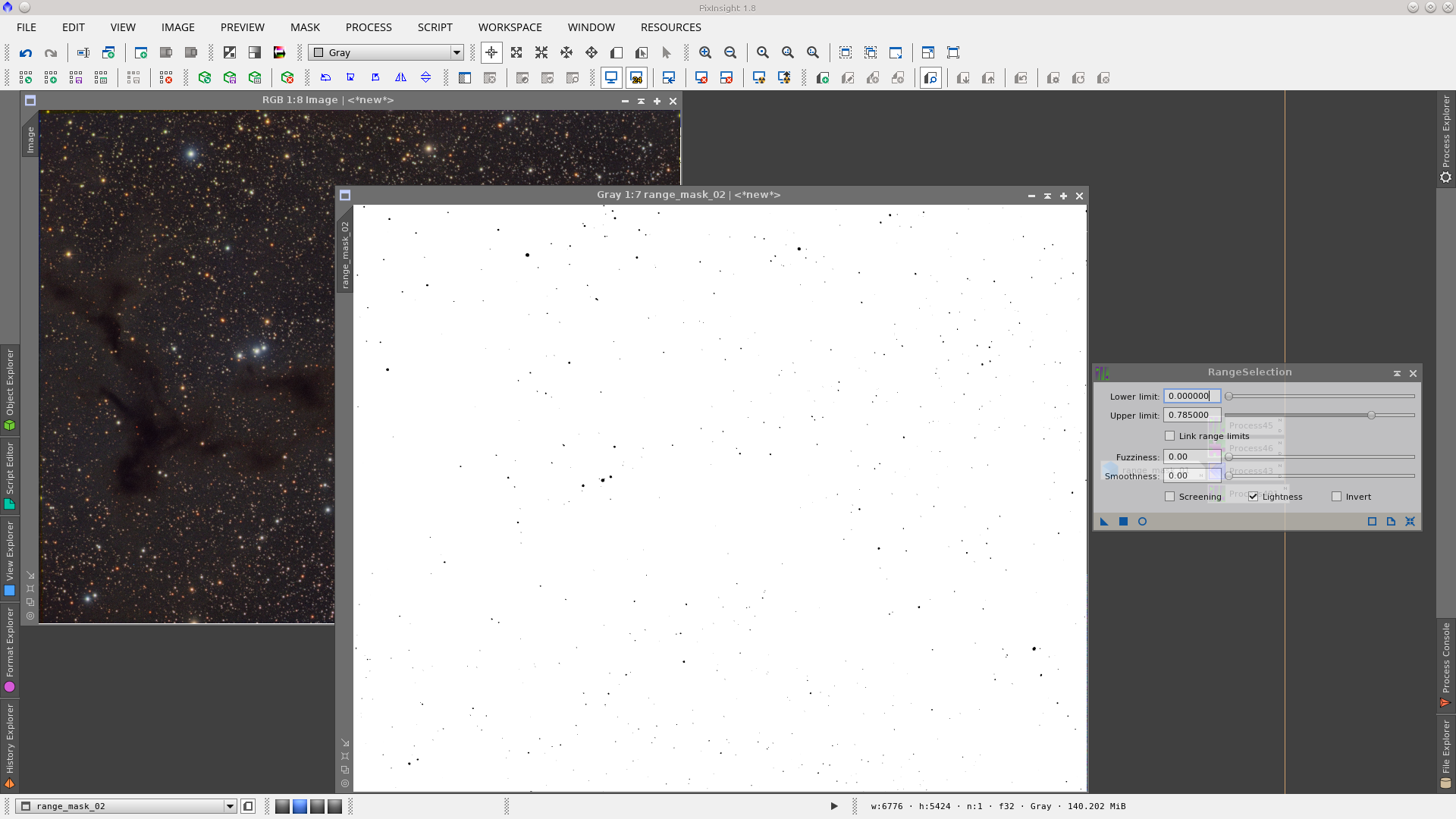
This second mask is more crucial to adjust if there are stars inside the radii of the halos. It is common to have little stars near big stars, and inside their halos, so you need to protect those stars to avoid processing them further. In this example I have decreased the Upper limit in the RangeSelection tool a little more to ensure those stars are in the mask.
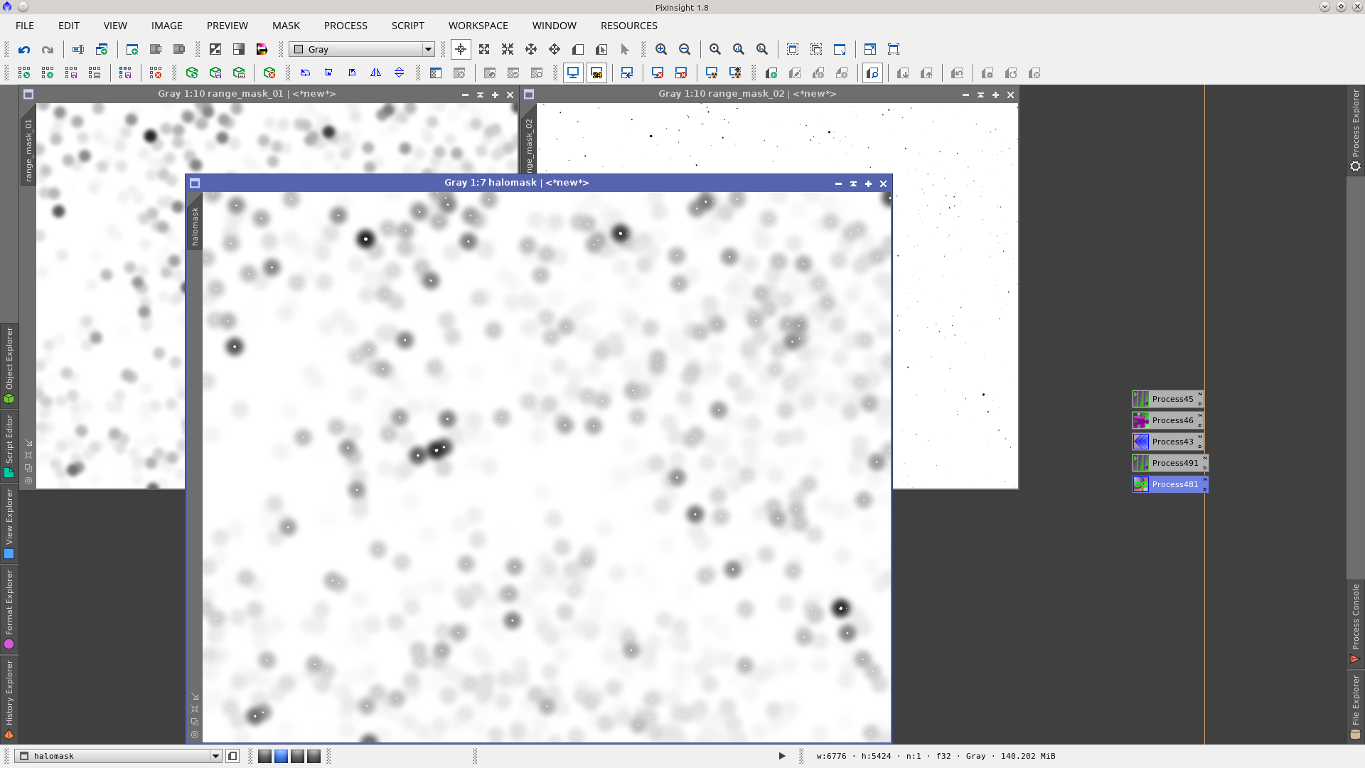
At this point we have two masks, rangemask_01 which represent the halos of the stars and rangemask_02 which represent the cores of the stars. Using PixelMath we will obtain the final HaloMask.
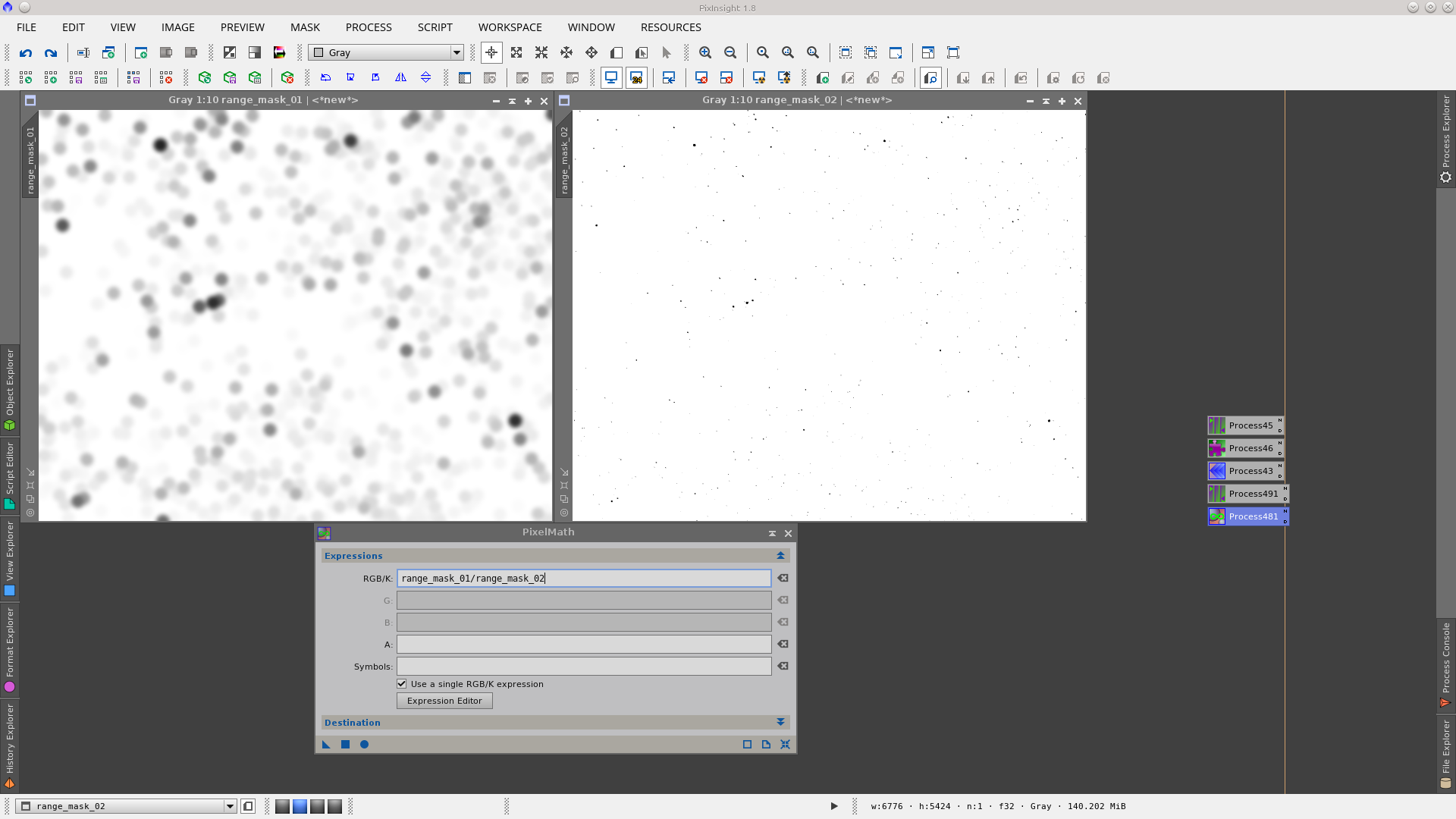
The values of the pixels in the rangemask_02 are 1 in the background and 0 on the stars, so if we divide rangemask_01/rangemask_02 we will obtain an image where the values in the center of the stars will be one, the same as the background.
This HaloMask needs to be smoothed to have a better transition between the values of the pixels in the cores and in the halos, for which I use MultiscaleLinearTransform, deleting the three first layers.
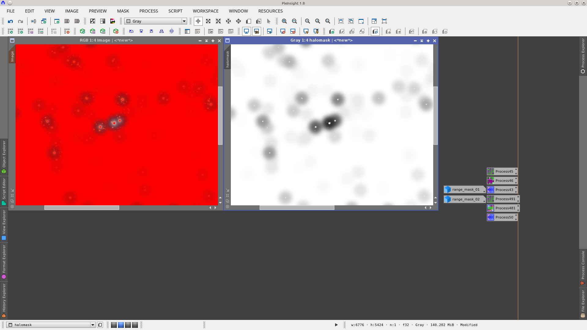
In order to protect the star cores and the background of the image, the HaloMask must be applied inverted. This way, the values that are 1 in the mask will be 0 when inverted, representing points of full image protection, and the halos will remain with intermediate pixel values (between 1 and 0) and will be points where the processes will be partially applied. It will look like the following screenshot:
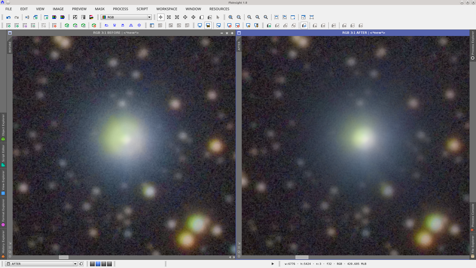
Now, using the HaloMask you can apply different processes to work on the halos of big and medium size stars. In this example I used various configurations of the MorphologicalTransformation tool and got the result below. See how the big star is reduced in diameter:
Here is another area of the image where the big star halos are reduced while the little stars inside the halo of the big stars remain unaffected.
Terrestrial Mask
A Terrestrial Mask is an easily made mask that allows you to work independently on the ground and the stars in a typical image of landscape with stars. For instance, if you have mountains and sky and the objective is to add several images to obtain a good SNR in both, this mask will be necessary for adding those images while protecting the moved (rotated) and partially rejected mountains.
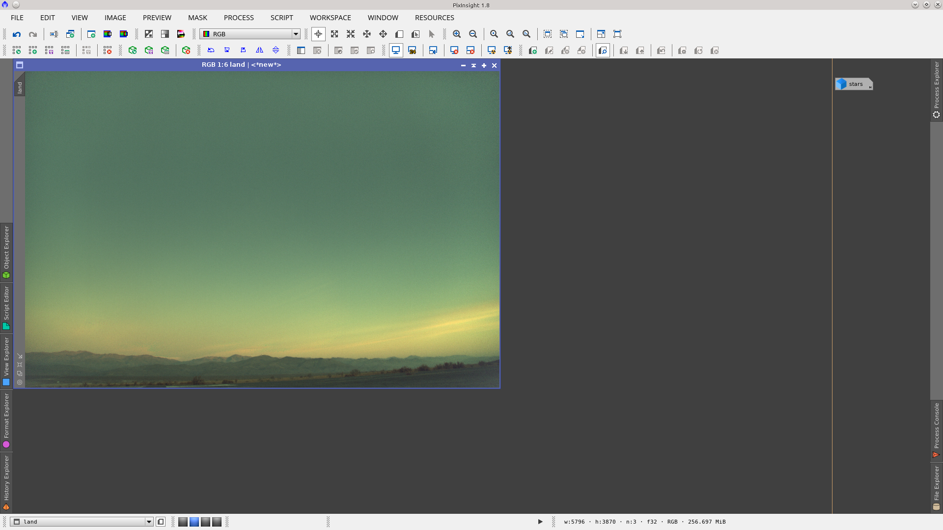
In this example we are considering two images, one is an integration of a set of images during the sunset called "land" which has the information of the mountain. This image was conveniently corrected with DBE to reduce vignetting.
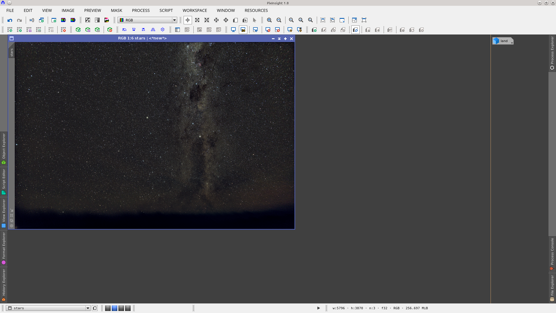
The second image is called "stars" and is an integration of another set of images taken from the same position later in the night. This group of images were aligned on stars so the mountains moved in every registered image, causing them to be partially rejected in the integration.
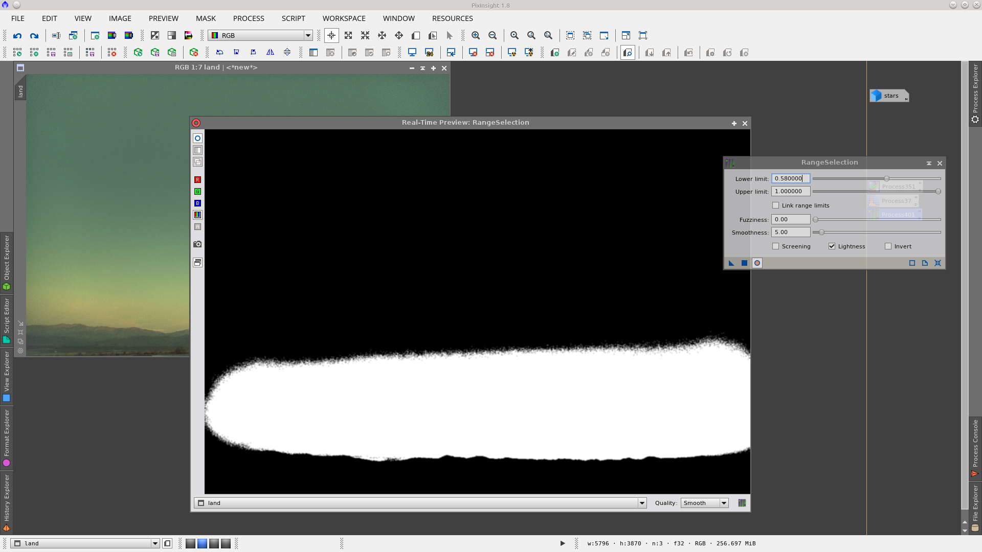
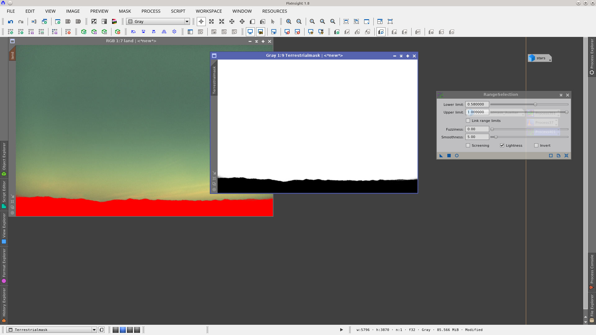
You can generate a terrestrial mask using the RangeSelection process over the "land" image. However, in most cases the pixel values of the ground are similar to values of the darkest areas of the sky. Also you may have the additional complexity of some residual vignetting if you did not use flats (as in this example) which complicates the separation.
Applying RangeSelection you can see that the mask covers both the mountains and the darkest pixels of the sky, and we want to have a mask with only a representation of the mountains.
This article shows several ways to generate gradients. The idea is to first generate an auxiliary terrestrial mask with a gradient to protect the image, over which we want to generate the range mask while applying a non linear stretch on the unprotected region.
Rotate your "land" image 90º clockwise.
Open the PixelMath tool and write the following expression in RGB/K:
log2(X()+h)/(1-$T)
Include in Symbols: h (the value that best adjusts the sky shadows to the tops of the mountains (your terrestrial object)).
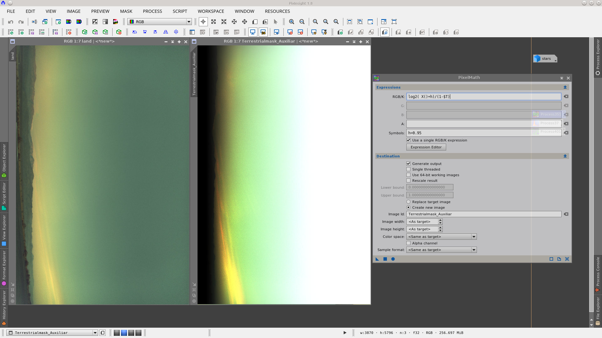
In Destination select "Create new image" and drag and drop the PixelMath process over the image.
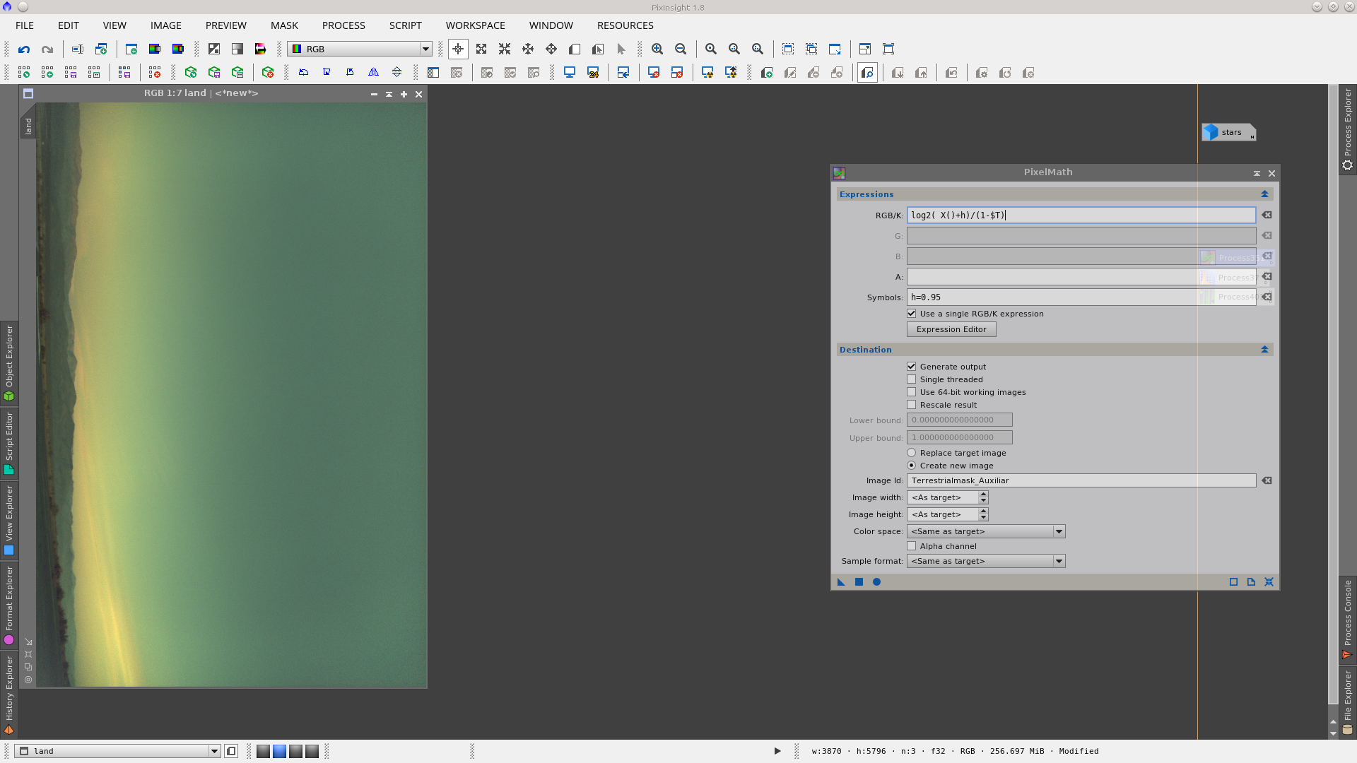
This will generate and auxiliar mask where the values of the pixels in the mountain will be considerably lower than the values of the pixels in the sky.
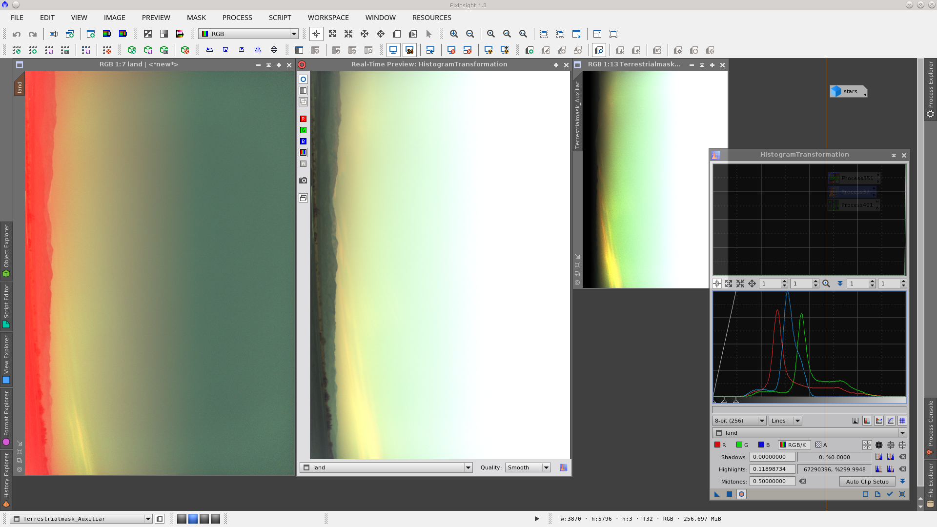
Apply this auxiliary mask to your "land" image protecting the mountains, and stretch it easily using the HistogramTransformation tool.
Now you can generate the terrestrial mask over the stretched "land" image and the result will be a well defined silhouette of the mountains as can be seen in the following Real-Time Preview of the RangeSelection tool.
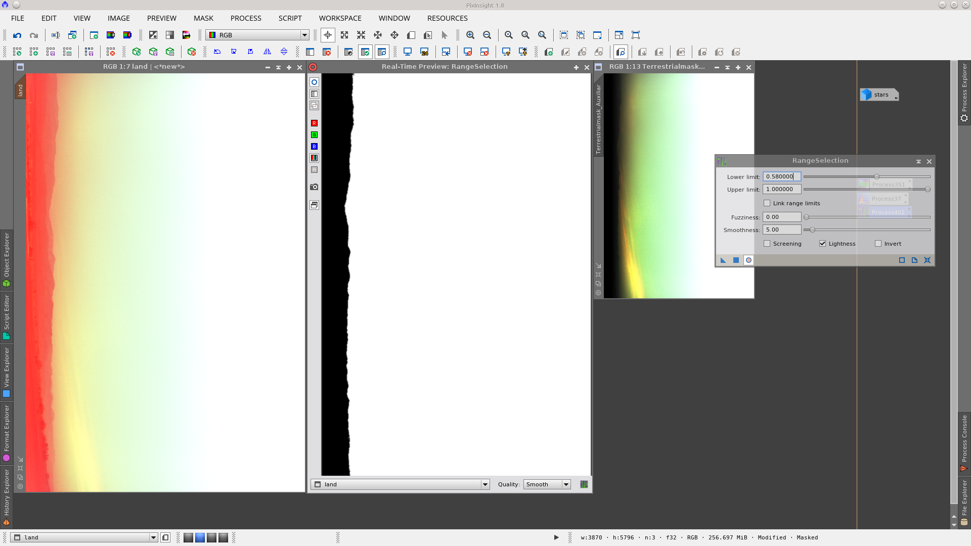
Apply the RangeSelection tool and generate the mask. For the final composition of the image, rotate the terrestrial mask 90º counterclockwise, undo the modifications made to the "land" image, and apply the mask protecting the mountains.
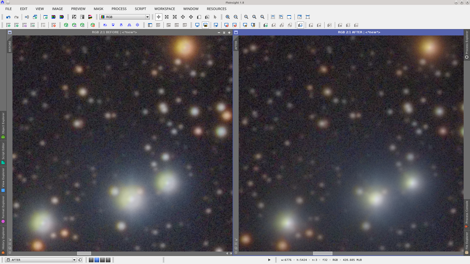
Do the necessary processes to the "land" image and finally, while protecting the mountains with the terrestrial mask, add the "stars" image using PixelMath.
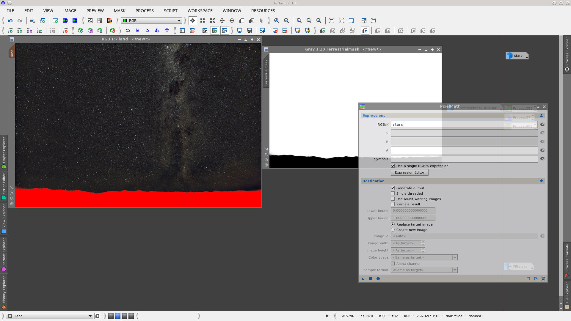
Final composition:

Circular Mask
A Circular Mask is basically a circle that you can use to protect a region of interest in an image. The typical use involves the Sun. In Sun images (taken with appropriate equipment) you may be able to enhance solar flares using a mask to protect the disc of the Sun. It is also useful to protect the background while you give color to the Sun.
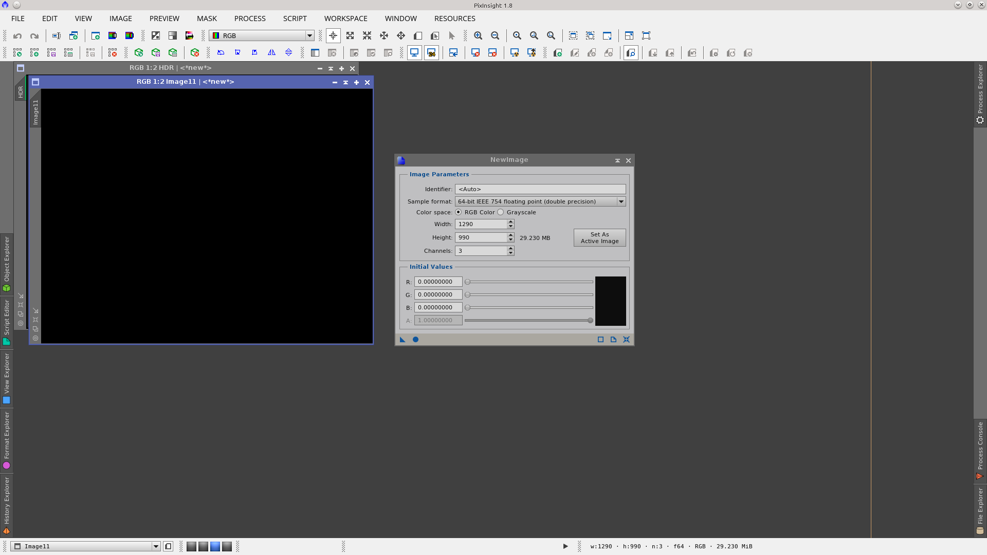
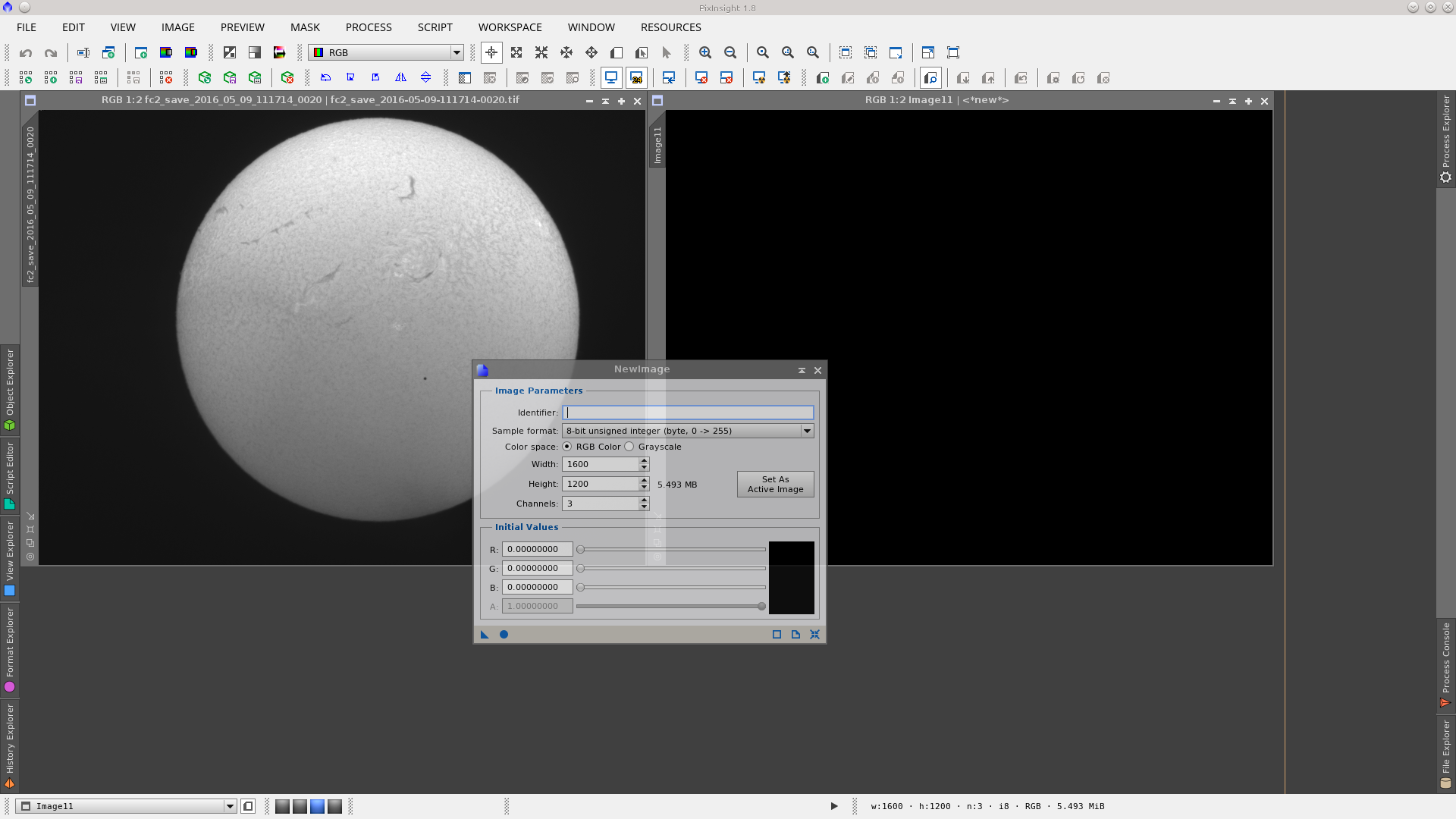
To build a Circular Mask, first generate a new image with the same dimensions as the image you want to protect. The easy way is to open the NewImages Module (Process > Images > NewImage), or from the Image Menu (Image > New), or by using the CTRL + N hotkey.
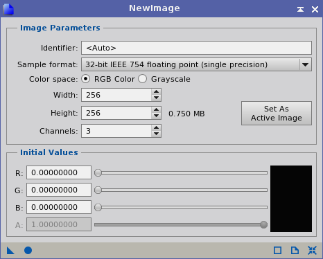
Press the Set As Active Image button in the New Image module to have the new image with the same size that as image you have acquired (which must be open on the workspace). Apply Global button (F6) and you will get a black image.
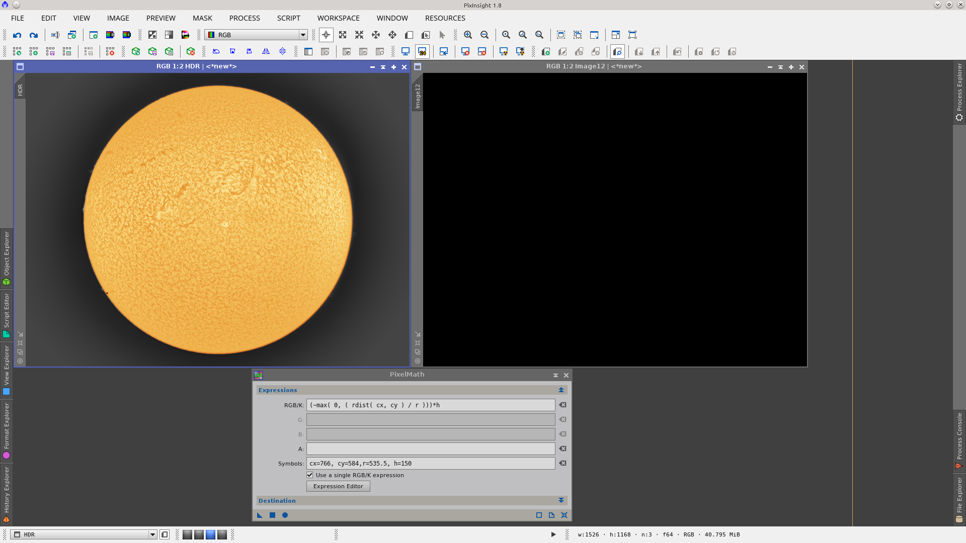
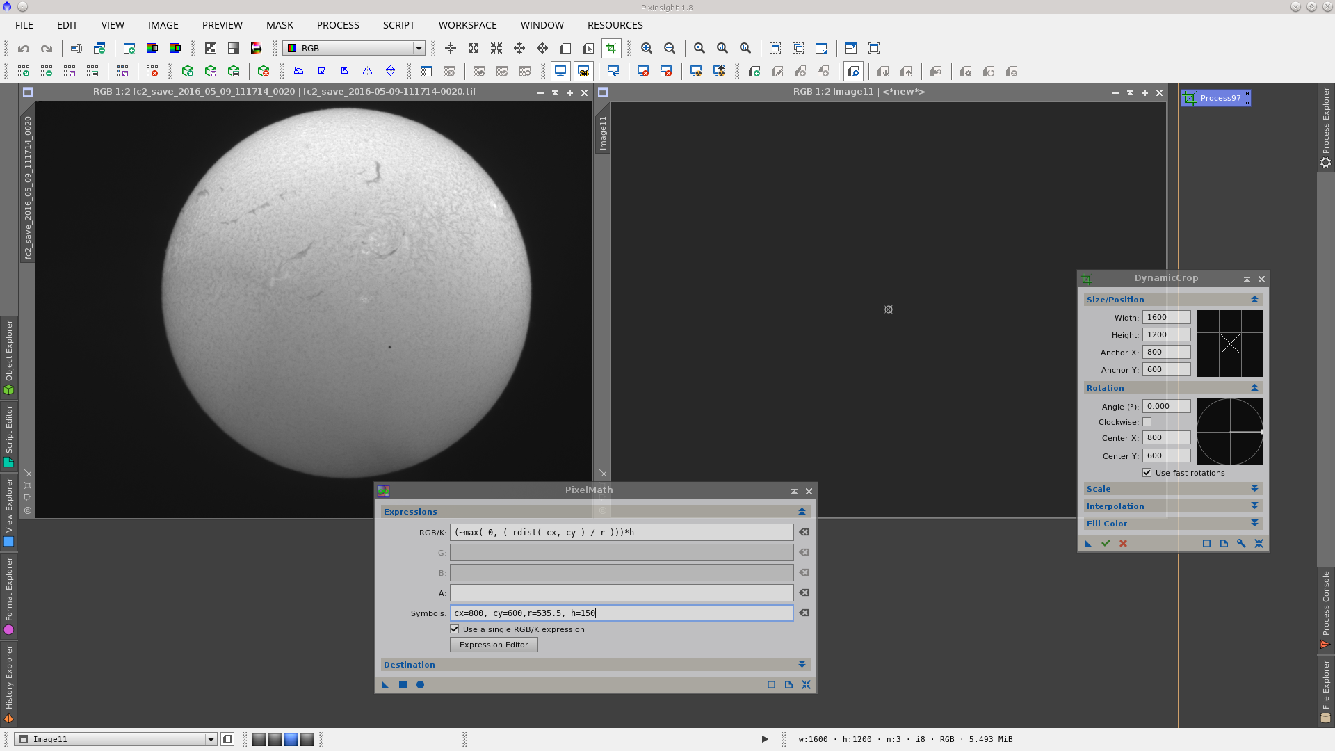
Open the PixelMath tool and write the following expression in RGB/K:
(~max( 0, ( rdist( cx, cy ) / r )))*h
Include in Symbols: cx (the value in pixels of the x coordinate of the center of the circle), cy (the value in pixels of the y coordinate of the center of the circle), r (the value in pixels of the radius of the circle), and h (to define the border of the circle: the bigger the value, the sharper the edge).
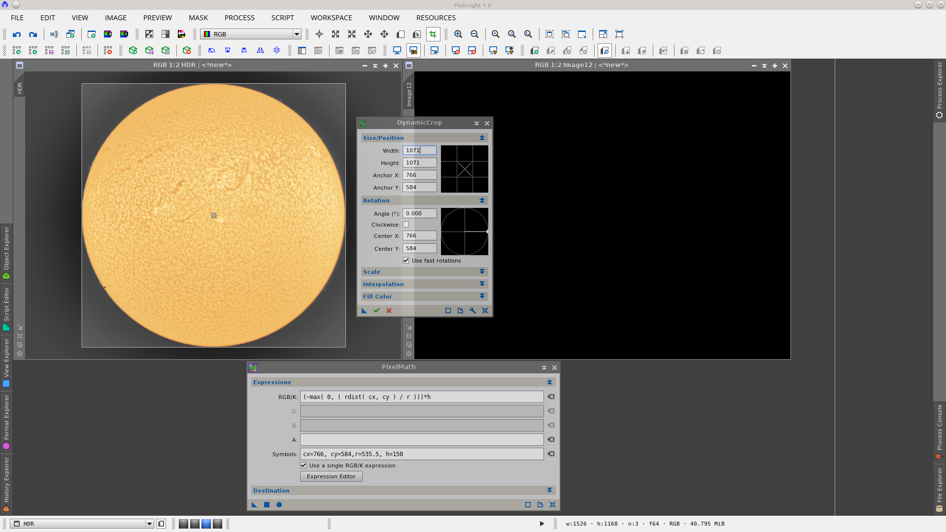
You can read the coordinate values directly by hovering the cursor on the image and reading them on the Position tool bar or by using the DynamicCrop tool. The latter will give you a more precise value.
Click on the image to focus on it and open the DynamicCrop tool. Reset it and adjust the borders to fit the Sun. In the Size/Position section of the tool you can read cx and cy values and calculate the radius by dividing the width or the height by 2 (you should have a square with width = height).
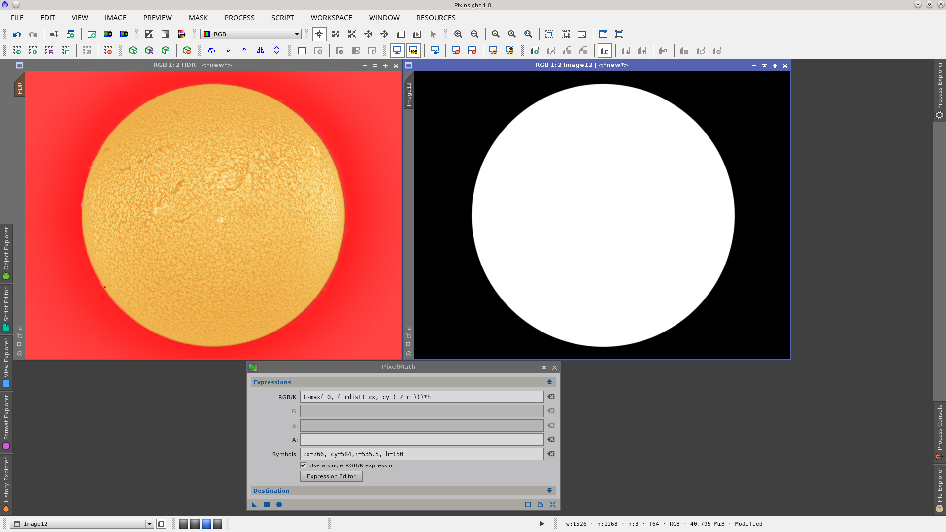
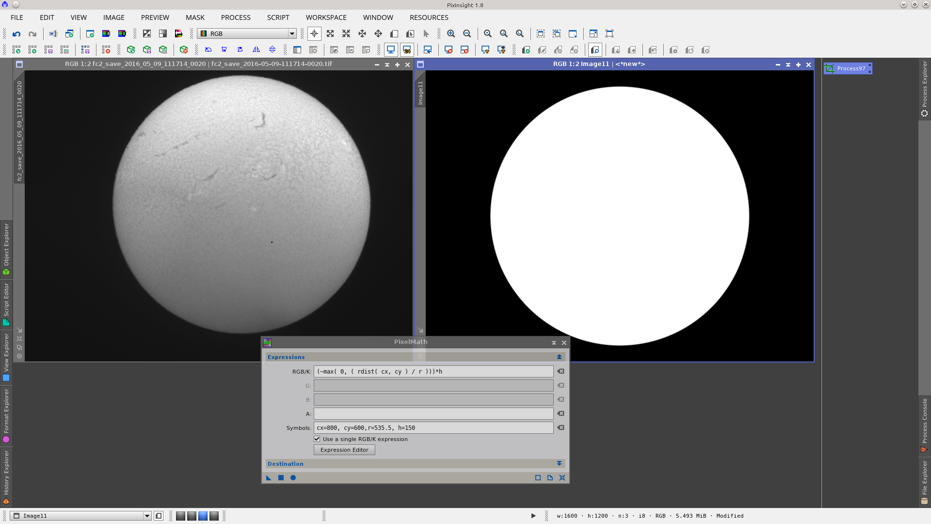
Apply the PixelMath process on the black image and you will get the circle located in the correct position of the image. If you need to make some adjustments simply correct the value of cx, cy, r or h and apply again on the same image.
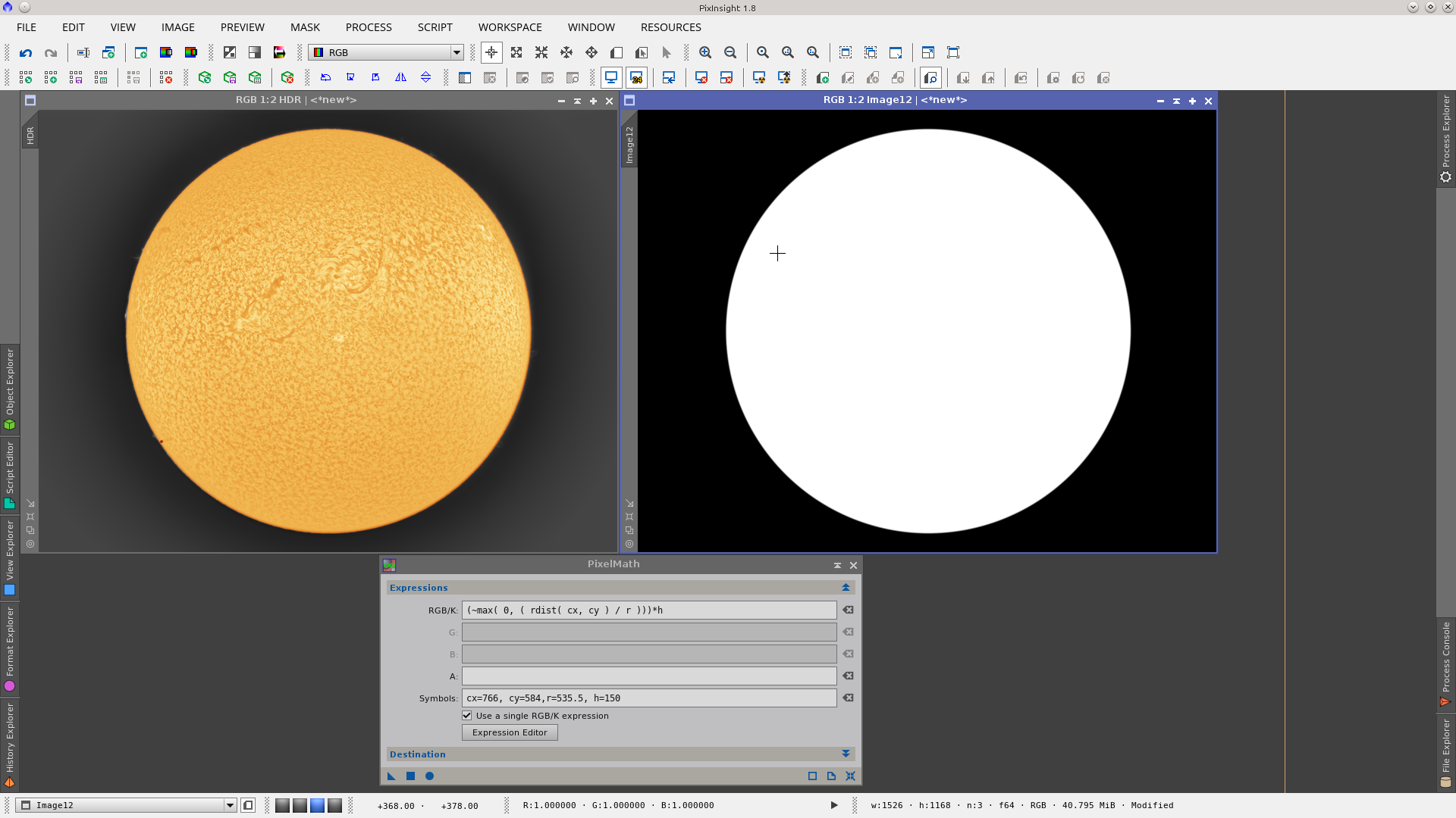
Tip: It is very useful to apply the mask, visualize it, and make the needed corrections to the mask while it is applied. This will let you see every minor adjustment.
Circular Mask as reference image
A Circular Mask can also be used as a reference image to align a set of Sun images. It is very common in long sessions of Sun images like transits, eclipses, or when following the movement of the Sun to have several set of images with the Sun in different positions, and the usual need is to align all of them in the center of the image.
To perform this task, first open one of your Sun images. Generate a Circular Mask that will work as the reference image. The tool of choice is PixelMath as it lets you locate the Sun perfectly in the center of the image.
First generate a new image with the same dimensions as the acquired images. The easy way is to open the NewImages Module (Process > Images > NewImage), or from the Image Menu (Image > New), or by using the CTRL + N hotkey.
Press the Set As Active Image button in the New Image module to have the new image with the same size as the image you have acquired (which must be open on the workspace). Apply Global button (F6) and you will get a black image.
Measure the diameter of your Sun and calculate the radius (r). You can read the coordinate values directly by placing the cursor on the image in the border of the Sun and reading them on the Position tool bar or by using the DynamicCrop tool as was previously described.
In PixelMath write the following expression in RGB/K:
(~max( 0, ( rdist( cx, cy ) / r )))*h
Include these PixelMath Symbols: cx (the value in pixels of the x coordinate of the center of the circle), cy (the value in pixels of the y coordinate of the center of the circle), r (the value in pixels of the radius of the Sun), h = 150.
cx is the width divided by 2, cy is the height divided by 2, and r is the diameter divided by 2. h defines the border of the circle: the bigger the value, the sharper the edge. A value of 150 is appropriate in this case.
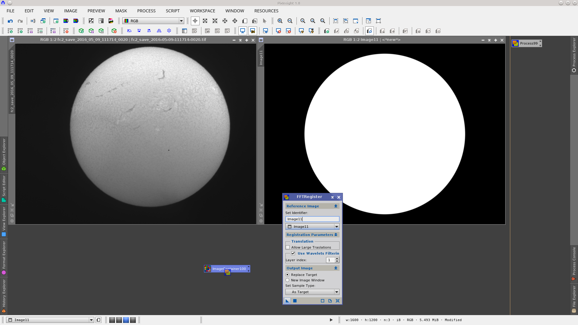
Apply PixelMath on the black image and you will get a reference image with a white circle in the center.
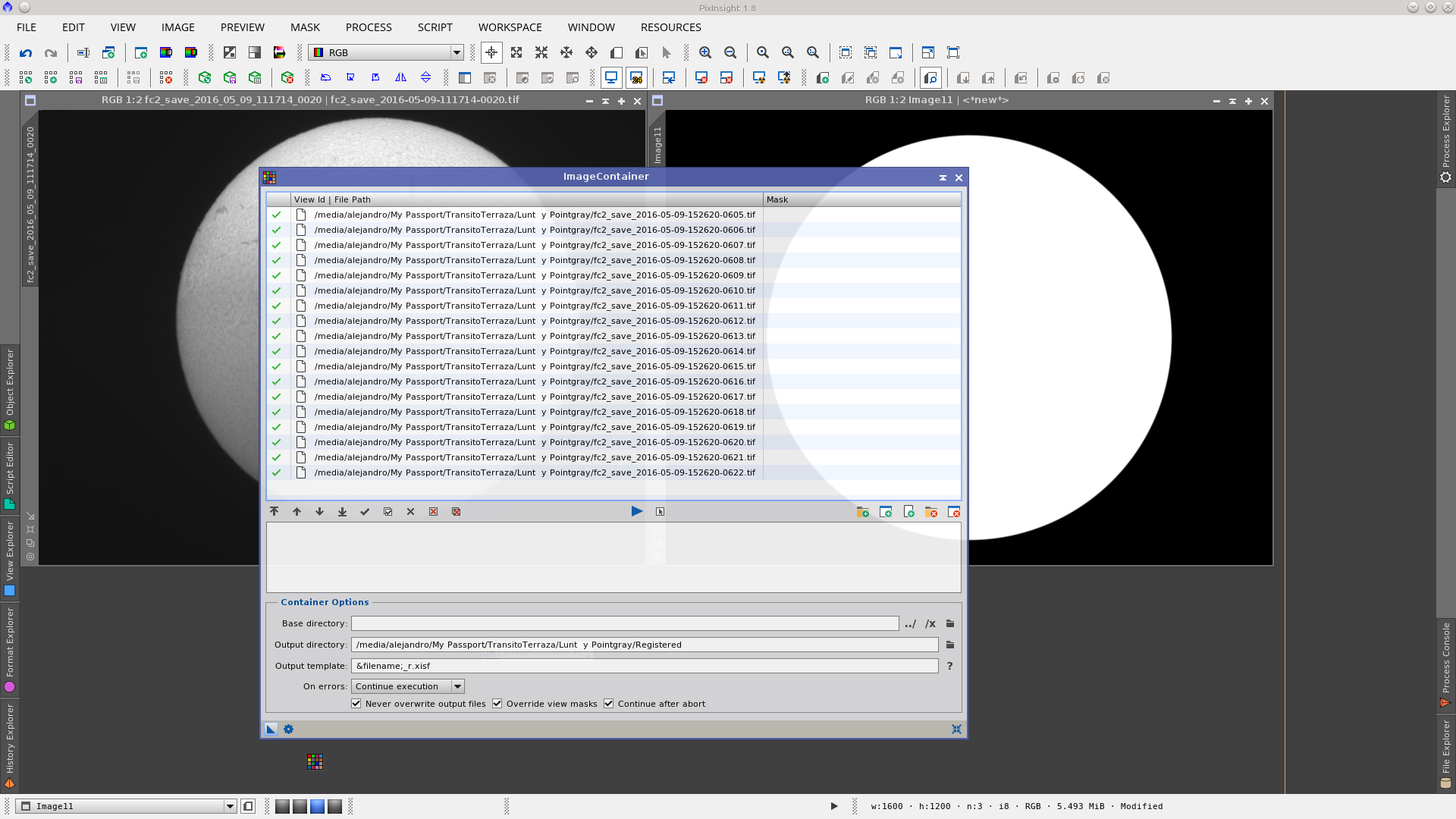
Open ImageContainer and add the images you want to align.
Select an output directory different from where your input images are located.
Specify an output template, for example:
&filename;_r.xisf
Generate the ImageContainer instance on your Workspace.
Open the FFTRegister Module (if you do not have it, see how to get and install Carlos Milovic's modules here)
Set the identifier: here you should select the reference image that was created with PixelMath above.
Layer index: set the value to 1
Output image: set "Replace Target" (This is important and will avoid replacing your images since you have already selected a new location in ImageContainer)
Apply the FFTRegister Module over the ImageContainer instance.
You can further inspect your aligned images _r using the Blink Tool and continue making a video or with the integration you want to do.
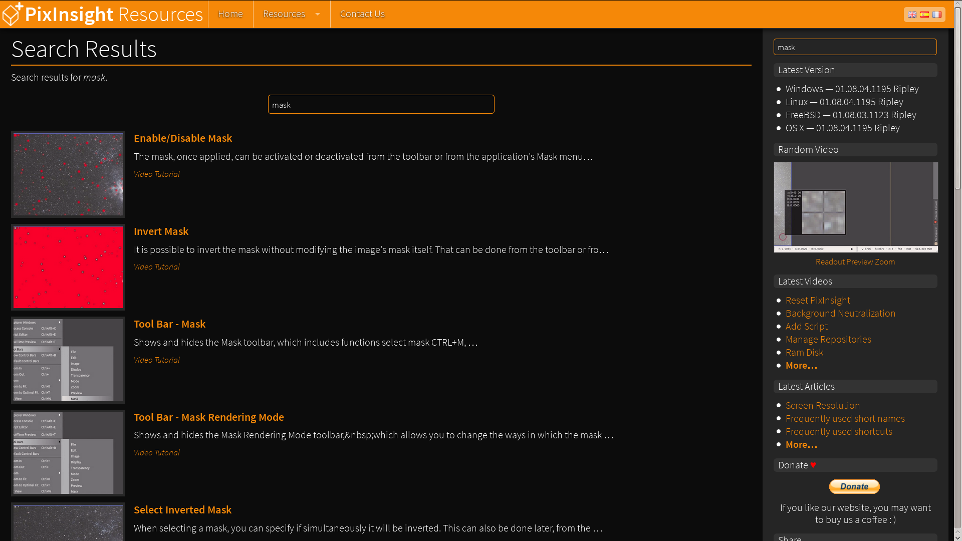
Finding Mask in PixInsight Resources
Writing the word "mask" in the search field of your browser or in the search field of the PixInsight Resources Home Page you will have quick access to many Video tutorials, Articles and Processing examples related to the use and creation of masks.
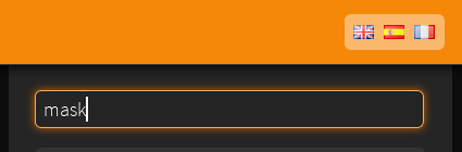
Click ENTER to have the complete list of the available resources:
Applying Masks
To apply a mask over an image in PixInsight, the image and the mask must have the same dimensions, otherwise they will be incompatible. There are several ways to apply a mask:
- Menu Mask › Select Mask, with the main image active.
- Keyboard shortcut CTRL + M, with the main image active.
- Button Select Mask
 in the Mask toolbar.
 - Drag the image identifier and drop it on the view selector in the main image. The following video shows the procedure, which is usually the most convenient and the most used.
This method can also be used to apply an inverted mask by holding the CTRL key at the same time that you drag the image identifier and drop it on the view selector in the main image.
Note that the image identifier tab of the main image changes color when there is an active mask applied.
Masks have different states that can be controlled from the Mask toolbar:
- Invert Mask SHIFT + CTRL + I
 - Invert a mask only on an image. This does not change the mask, it only inverts it on a given image.
 - Enable/Disable Mask SHIFT + CTRL + M
 - Enable and disable the mask (does not split the mask from main image, it only activates or deactivates its effect). Note that the color of the image identifier tab switches when activating and deactivating the mask.
 - Show Mask CTRL + K
 - Shows and hides the visualization of the mask on the main image. The mask is shown on the image to view the areas to be protected (the default mask color is red, which can be changed from the toolbar Mask Rendering Mode or from Mask › Rendering Mode menu).
Note that the mask may be active and hidden (not visible but having an effect), or may be inactive and visible (visible, but having no effect). The status Enable/Disable Mask and Show Mask are independent. Check the status of the buttons in the toolbar (active/inactive) and the color of the image identifier tab to see the state of the mask.
To remove a mask (unlink the main image from the mask) the Remove Mask ![]() button may be used Remove Mask Remove Mask from the Mask toolbar, or you may use the menu option Mask › Remove Mask.
button may be used Remove Mask Remove Mask from the Mask toolbar, or you may use the menu option Mask › Remove Mask.
See video tutorials related to masks.
¿Questions?
More tutorials on masks
References
PixInsight Reference Documentation - HistogramTransformation
PixInsight Reference Documentation - RangeSelection
PixInsight Forum